A Trip Down Memory Lane – Part 3
Welcome to the final installment of our trip down memory lane – A peek into the pages of Modern Motor Magazine and the project car that started the ball rolling for Haltech. If you missed parts one and two, you can catch up here and here.
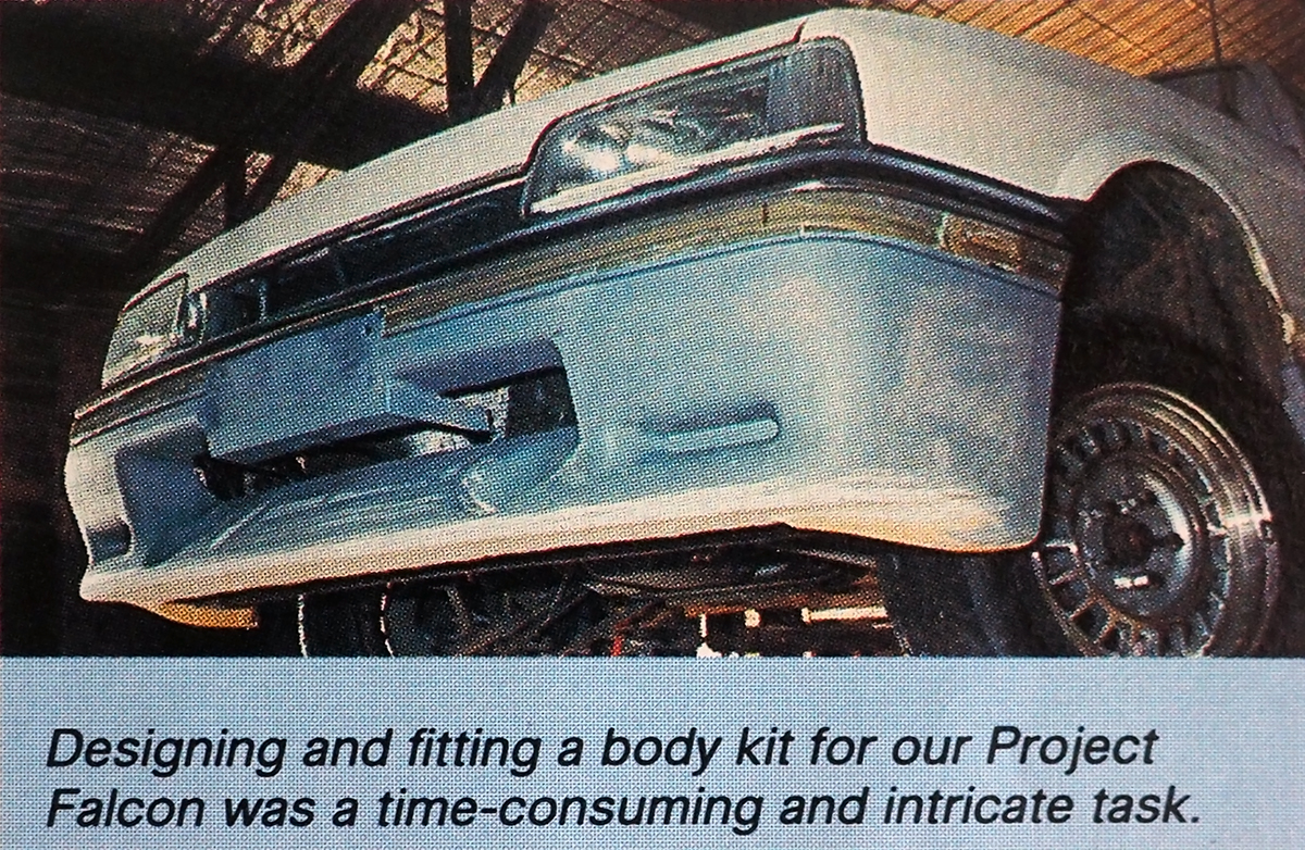
By the time November 1987 rolled around the Mobil Modern Motor Supercharged Falcon was ready to hit the streets. Wrapped in a new body kit, penned by ex-Holden stylist John Learson, it certainly looked fast. It wasn’t all show and no, go, however – The XF had the muscle to match the make-over.
The Sprintex Supercharged straight-six made 1980s V8-style grunt with 180kw at 4000rpm, and 435Nm at 2500rpm. It accelerated to 100km/h in 8.65 seconds and did the standing 400m (near enough to a quarter mile) in 15.56 seconds at 144km/h (89.5mph).
One thing it wasn’t though, was cheap. Including the purchase price of the original vehicle, the estimated bills came in at around $53,000 – That’s $8,000 more expensive than a brand new Holden HDT Group Three Commodore was!
Below is an excerpt from Part Four of the Project Car build, as published in the June 1987 Issue of Modern Motor, this breakout was written by Haltech founder, Steven Mitchell himself. Republished with permission from ARE Media.
Computer Program
THE Ford EEC4 engine management system was first introduced in America in 1983 on the Escort 1.6 litre and turbocharged 2.3 litre engines. Later it saw service on all Ford, Mercury and Lincoln engines with fuel injection and on the carburettored engine used in Mustangs, Capris, LTDs and Marquis’.
In Australia, the system is used with a vane airflow meter on the Falcon and with a manifold pressure sensor on the F100 range. When these systems first appeared in Australia I successfully contracted to several Ford dealers to diagnose electronic faults which they were having trouble with at the time and as a result I am very familiar with the EEC4 system.
There are three distinct problems to be solved to allow the Mobil-Modern MOTOR Falcon to be successfully supercharged:
1. The basic fuel delivery curve must be accurately extended to cope with the increased airflow.
2. The ignition timing must be regraphed for maximum efficiency without knocking.
3. The constricting effect of the standard vane air flow meter has to be removed.
The brain of the EEC4 system is the Electronic Control Assembly (ECA). This microcomputer acquires information from engine and transmission sensors and selects a strategy with which to control fuel delivery, ignition timing, idle speed and emission controls.

We considered designing an ECA to suit our requirements but this produced two problems. The standard Falcon fuel injectors can only flow an extra 10 per cent more fuel than the standard vehicle uses and would have to be replaced with larger injectors. Larger injector capacity implies lower accuracy in fuel delivery for the same injector control circuitry. The ECA is a complex device and much effort would go into simply duplicating the low end performance the standard Ford unit provides. We do not wish to re-invent the wheel.
This led us to the more standard approach of adding a second fuel injection system to take up when the Ford’s own system runs out of steam. Once. the supercharged airflow exceeds the maximum airflow reached by a standard engine, the pivoting vane airflow meter will be wide open and the standard management system will continue to inject the same quantity of fuel per injection regardless of increasing airflows.
The additional fuel injection system starts to function at the point where the standard system tapers off so as to allow the fuel delivery curve to smoothly continue. This additional system will measure inlet manifold vacuum rather than airflow. Manifold pressure related to the volume of air flowed by the velocity ratio of the inlet manifold, is a constant for a given manifold design. This systern will inject the additional fuel by means of two injectors positioned downstream of the supercharger.
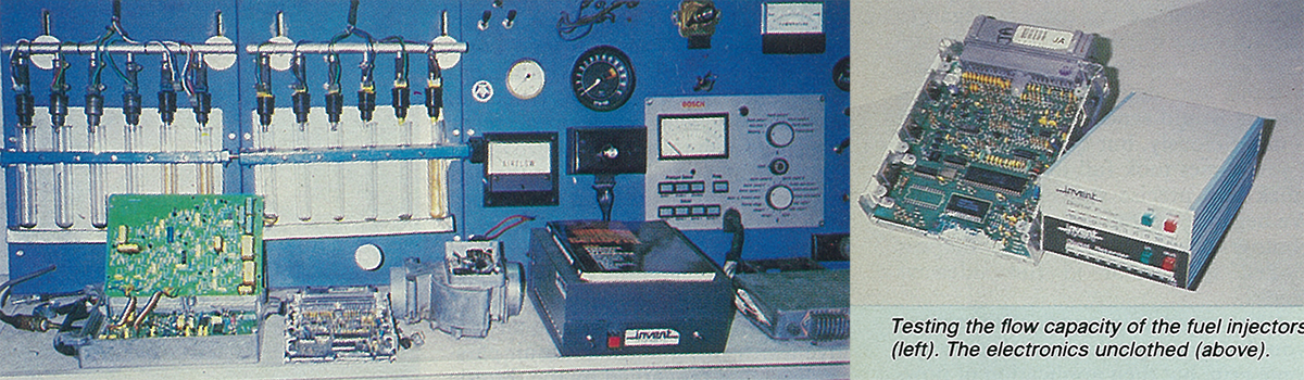
The basic fuel delivery curve used by this additional system will be stored digitally in a “read only memory”. With the car on the vane dynamometer and the necessary gas/ignition analysers connected, this fuel delivery curve will be set by means of an external computer capable of changing the curve with the vehicle running.
This basic fuel delivery will then be multiplied to correct for variations in engine temperature or inlet air temperature. Once a curve is fixed, a ROM chip is “burnt-in” so that it can not be tampered with while in service on the vehicle.
The ignition timing is set by the ECA. The distributor sends the ECA a stream of pulses (profile ignition pulses) synchronised to when each piston reaches IO degrees before top dead centre. Accurately knowing where 10 degrees before top dead centre is, the ECA times out the correct position to fire the electronic thick film ignition module and hence determines the ignition timing.
We have rotated the distributor so that the profile ignition pulses occur 20 degrees before top dead centre. We have then placed an electronic delay between these profile ignition pulses and the ECA. If we delay the PIP pulses by 10 degrees then the ECA will see them occur at the normal 10 degrees before top dead centre, (i.e. 20 degrees static timing -10 degrees of delay equals 10 degrees static timing).
If we delay the PIP pulses by more or less than 10 degrees then we have effectively retarded/advanced the ignition timing. This new ignition timing map is stored in another “read only memory” and will be set in much the same way as the fuel delivery curve once on the dyno.
The standard management system is fitted with an anti-knock sensor attached to one of the front head bolts. Once this senses engine predetonation the ECA alters the ignition timing by a fixed amount to eliminate the knock. This is done partially at the expense of engine performance. These sensors may detect a “phantom” knock which can cause an unexplained flat spot on acceleration as the ECA tries to eliminate non-existent predetonation. We have disconnected this knock sensor and have in mind several alternatives to deal with the problem of predetonation.

And that brings us to the end of our three-part journey! Unfortunately, we don’t have any information as to what fate befell the Mobil Modern Motor Supercharged Falcon once the magazine feature came to a close, but we like to think it is sitting in a shed somewhere out there in the Aussie outback, just waiting to be rediscovered and brought back to life.

