Installing a stand-alone iC-7 dash
Whether it’s a mechanically injected monster, or a reliable, carbureted cruiser, the Haltech iC-7 standalone “Classic” kit is a great option for modernizing your old dash cluster. Today’s patient is this 1986 Jeep Wagoneer and we are about to breathe new life into this classic ride by upgrading it to the Haltech iC-7 colour display.
With its digital fuel gauge, customisable screen layouts and plug and play compatibility with other Haltech CAN devices, this upgrade really was a no-brainer. Below is a quick, step-by-step guide on how we got it done.


What you get with the Standalone iC-7 Kit
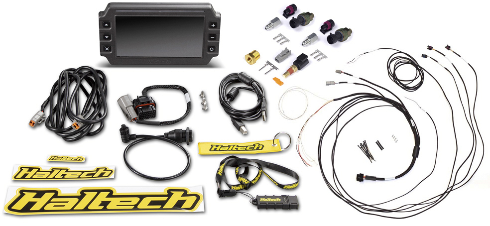
Apart from the 7″ digital display dash, the iC-7 Standalone “Classic” Kit includes a sensor pack, 34 Pin main connector harness, DTM-4 to DTM-4 CAN extension cable, USB to M5 right angle cable and a semi-terminated iC-7 harness.
The standalone iC-7 harness includes connections for three sensors of your choice, as well as a fuel level sender. It also has a connection for a vehicle speed sensor and a CAN connection port. This device is plug-and-play with our CAN-based tire pressure monitoring system TMS-4 and can also connect to our WB1/WB2 Wideband modules, or the TCA EGT modules. The sensor pack includes a coolant temp sensor 1/8 NPT, a brass adaptor 1/8″NPTF to 3/8″NPT and two 150PSI “TI” fuel/oil/wastegate pressure sensors.
Optional Extras
This Grand Wagoneer came with a carbureted AMC 360 V8 and a Chrysler automatic transmission. It’s mainly used for summer transportation and some light off-roading on the weekend. For this install, we are going to opt for a coolant temperature sensor, a fuel pressure sensor and an oil pressure sensor. We will also upgrade to the optional GPS Speed module as well as the CAN-based TMS-4 and WB2 systems.
Sensor Installation
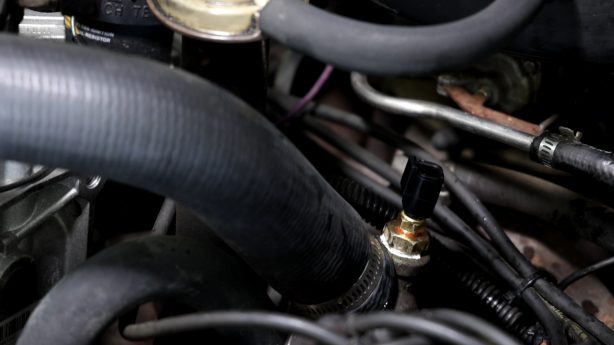
We need to scout out our sensor locations, luckily a quick web search found us the factory locations for most of these. The oil pressure sensor is a 0-150 psi transducer with a 1/8″ NPT connection; this will easily install the factory location on the passenger side of the engine block. A quick cleaning, a dab of paste, and we are ready to tighten and connect it to our standalone harness.
Our coolant temperature sensor is actually going on the water neck, there is a convenient 3/8″ NPT port. Using the included 3/8″ NPT to 1/8″ NPT reducer allows us to screw in the new sender. Finally, the fuel pressure sensor will go into our factory soft line connection just before the carburetor. A brass inline gauge port tee provides the 1/8″ NPT port required to install the sensor.
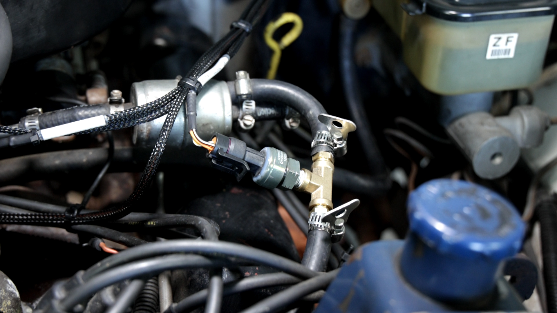
NOTE: This sensor is rated up to 150 psi and although this application is carbureted (5-7 psi), it will also work with mechanical systems that see much higher pressure readings.
O2 Wideband Sensor
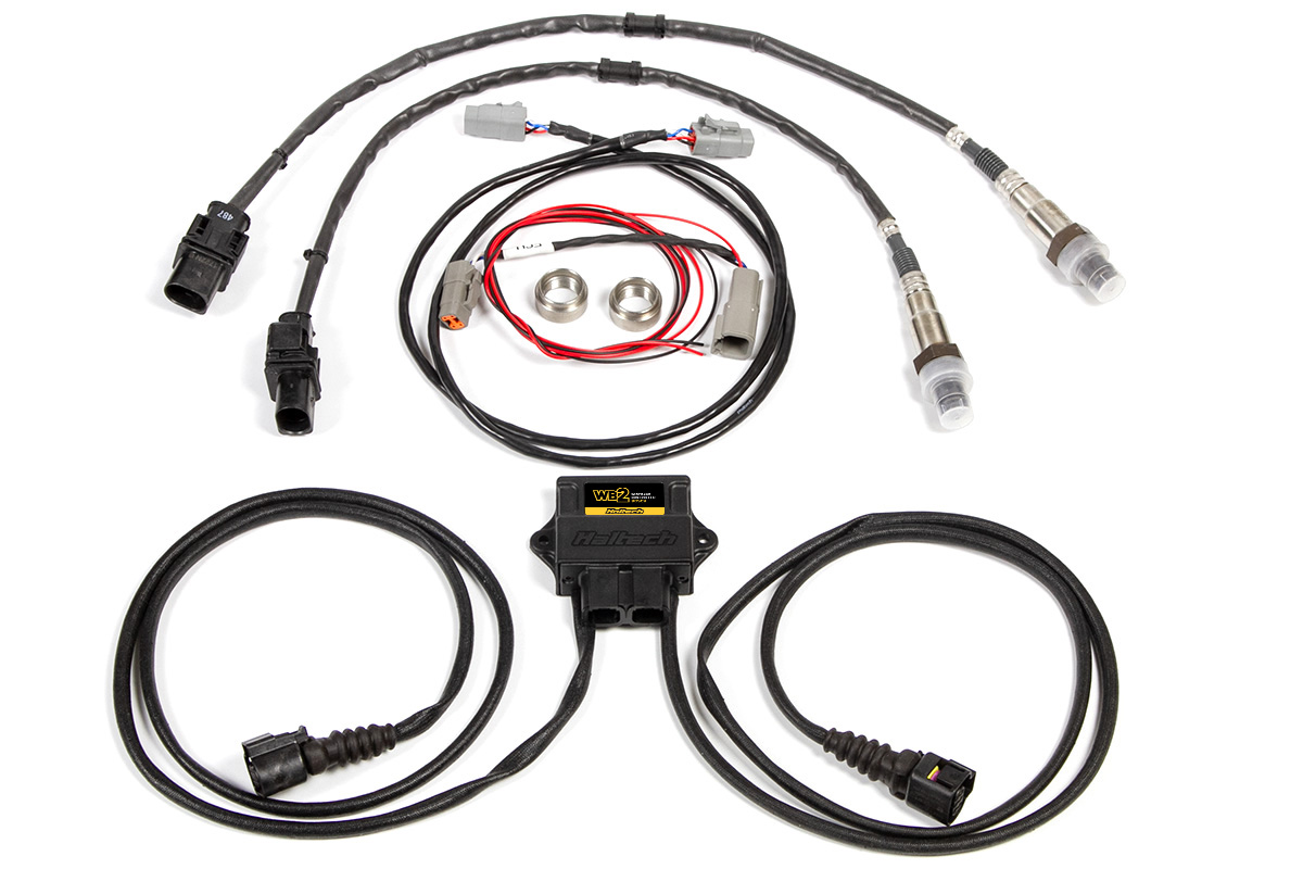
Now it’s time to get this thing in the air and get a WB2 wideband oxygen sensor module installed in the factory dual exhaust. While we are limited on tuning with the factory 2-BBL carburetor, the owner plans to use an aftermarket intake and 4-BBL carburetor in the future.
These sensors will be an awesome tool for dialing in performance after those upgrades. A good rule of thumb is to place the bung/sensor approximately 6-10″ AFTER the merge on one bank. For this application, that means after the manifold collector for each side.

It’s worth mentioning that the “FUEL LEVEL” input includes a pre-terminated connector and a flying lead wire giving us the ability to create a harness for the sending unit that can easily be disconnected if we need to drop/service the fuel tank. The ICC software is pre-programmed with a ton of popular ohm ranges, but a custom calibration table is included if needed.
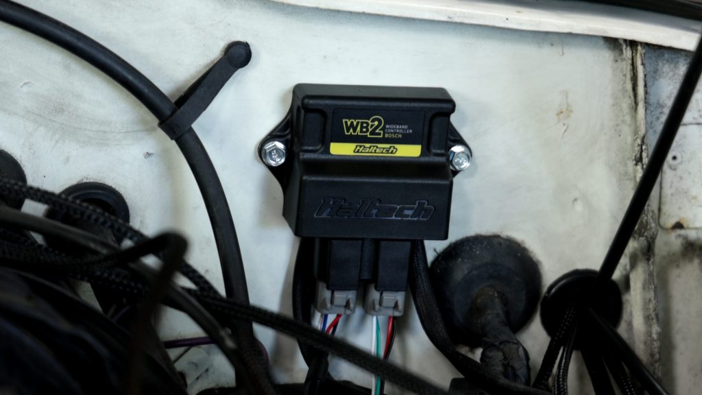
TMS-4 and WB2 Controller
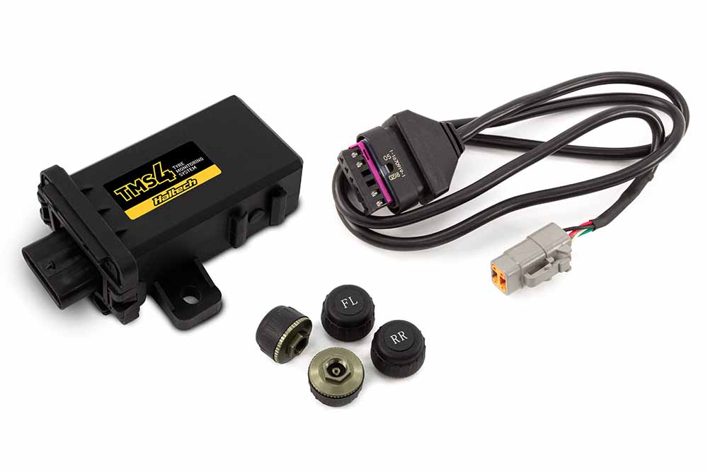
With the Jeep back on all fours, it’s time to install the tire pressure monitors. Haltech offers both internal or external sensors, but for ease of installation and quick interchangeability, we opted for external units. No calibration is needed once the TMS-4 module is connected to our display using the included CAN cable. Now it’s time to mount our WB2 and TMS-4 modules on the firewall, this gives us easy access to connect our CAN cables and connections for the dual wideband oxygen sensors.
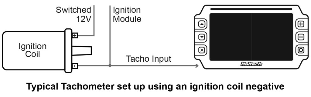
The only other thing to do under the hood is to wire in our engine speed input (Tach), luckily our factory ignition coil had a provision for a tach wire even though the stock instrument cluster didn’t show RPM. A quick spade connection on the standalone harness and we were finished with the engine bay.
In-cabin wiring
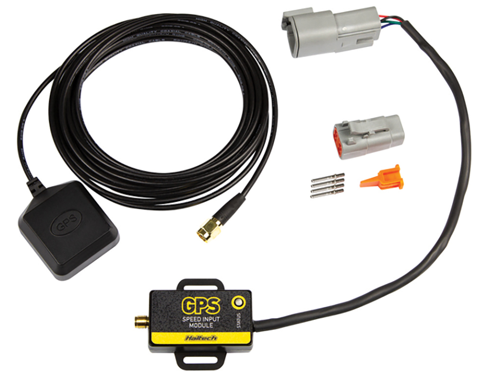
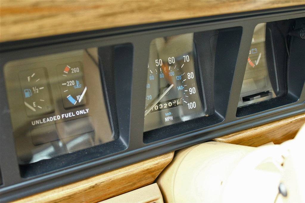
With our engine bay wiring and sensor installations complete, it was time to tackle removing the factory cluster and modifying the harness to adapt to our iC-7 display. Our Wagoneer used a mechanical speedometer cable, but after years of reliable service, it was time to upgrade to the GPS speed input module.
This plug-and-play device mounts an antenna with a single cable connection and calibrates with a simple check box in the Haltech ICC software. Not only will it register GPS speed (in mph or kph), it can also be used for odometer and trip meter readings.
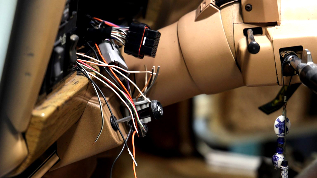
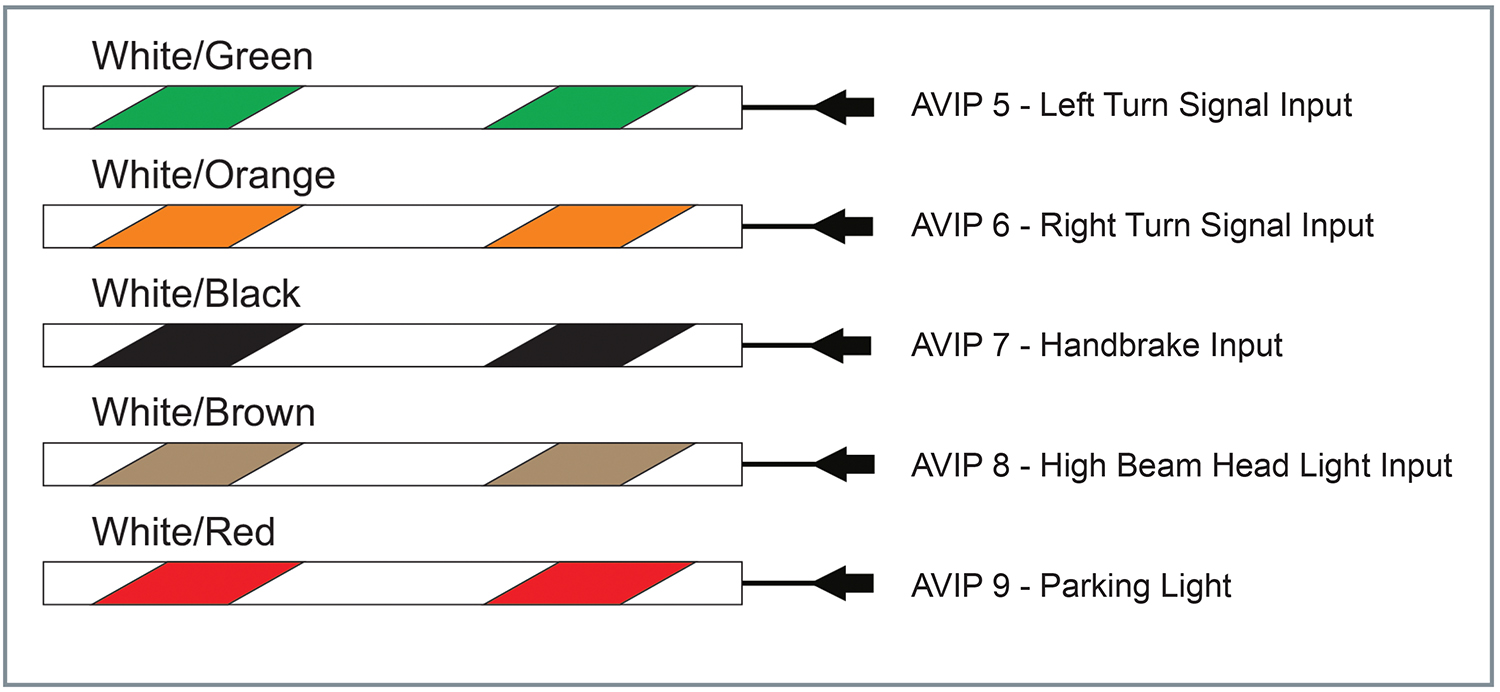
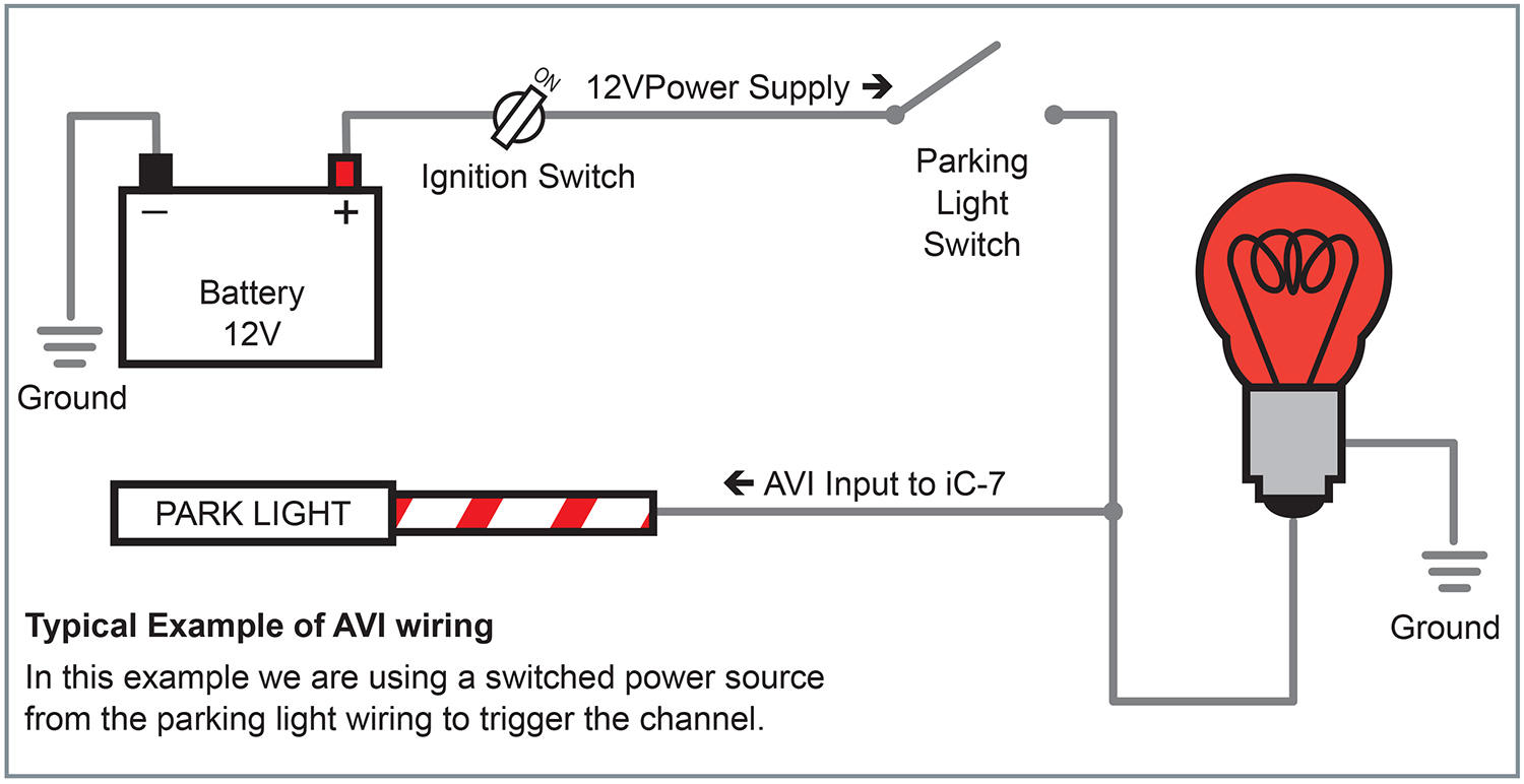
The factory cluster wiring gave us a nice selection to tap into for our accessories, including turn signals, high/low beam, and our fuel sender wire. We should note that with the exception of the fuel sender and the handbrake connection, all other inputs will be positive trigger-based. Reference the diagram below for an example of how to wire up your parking lights.
While a swarm of butt connectors could do the job, we felt it was better to wire in an 8-pin Deutch connector. This not only cleans up our dash wiring but also provides a simple disconnect in the event we need to remove our dash in the future. While we were at it, we ran the switched +12v and ground connections to our fuse block wrapping up all of our wiring.
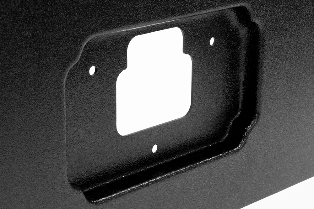
Final Details
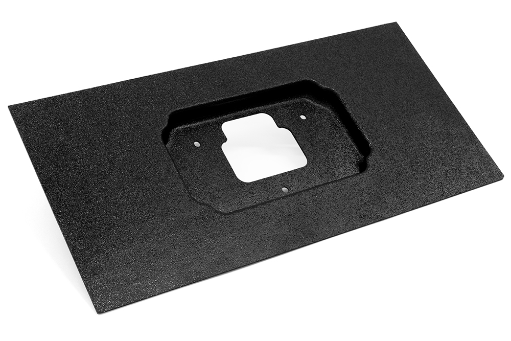
With the dash wiring completed, the only thing left to do was mount our 7-inch display. Using a universal moulded panel (sold separately), we created a bezel that attached to the rear of the iC-7 and allowed the cables to pass through. After making a few measurements and trimming, the bezel could use the factory mounting points and fit snugly into the Grand Wagoneer’s dash. And we’re done!
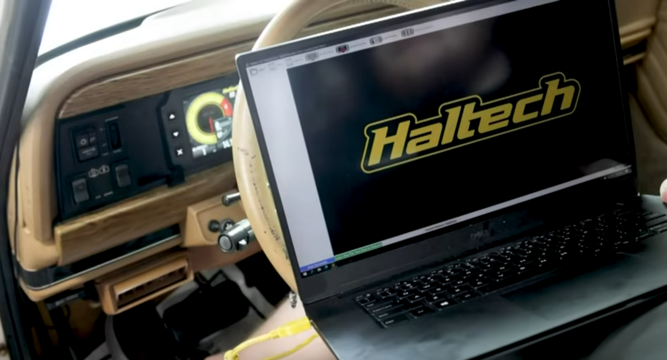
Software setup
The final step was to connect to our iC-7 display through the included USB communication cable and load the new standalone firmware through ICC. If you’re unfamiliar with our software package, read on to learn more about configuring sensors as well as other inputs!
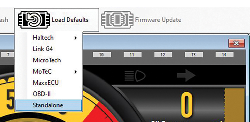
Loading iC-7’s Standalone Default
From the main screen click on the “Load Defaults” menu and select “Standalone”.
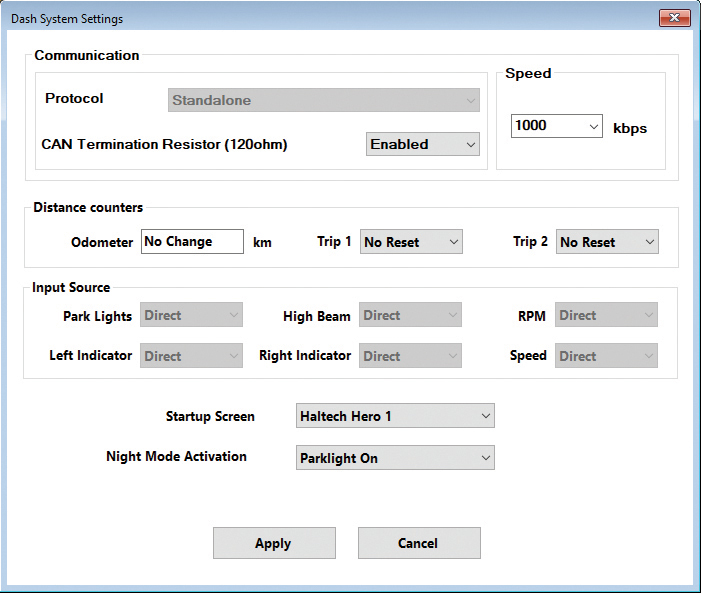
All the iC-7 inputs are now automatically set to “Direct” input mode.
Speedometer Input
The speed sensor provides a signal that, when received by the iC-7 can be used to display vehicle speed and/or set up speed-based alarms. The Haltech iC-7 harness will connect directly to a Haltech GPS Speed Input Module (HT-011310) without any additional calibration or configuration required.
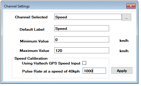
You can also connect your iC-7 to an existing OEM vehicle speed sensor. In the Channel Settings window untick the “Using Haltech GPS Speed Input” box. If you already know your sensor’s Pulse Rate (PPM), enter it and click “Apply”.
If you don’t know your sensor’s PPM calculate it using the following steps:
1. Ensure your speed sensor and iC-7 dash have a common power and ground supply.
2. Connect the sensor signal wire to “SPEED IN” (Pin 33).
3. Display the Speed Pulse Rate channel on an available gauge.
4. Drive the vehicle at 40KPH (25MPH) and note the Speed Pulse Rate value. You will need an external device (such as a GPS Speed smartphone app) to reference vehicle speed.
5. Enter the Speed Pulse Rate value in the relevant box and click “Apply” and you’re all set!
Tachometer Input
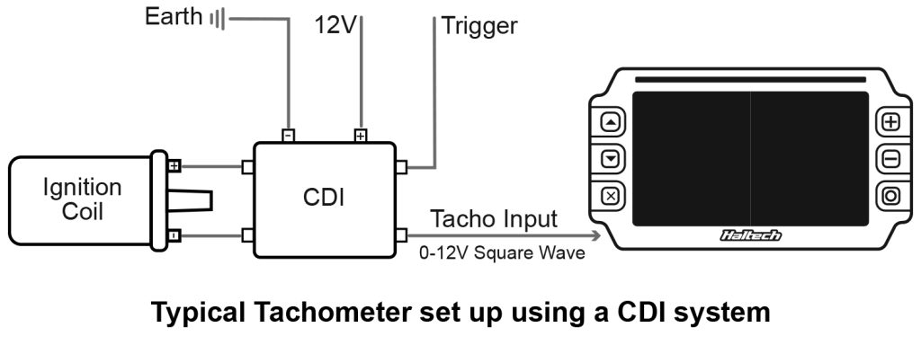
The “TACHO IN” is used to supply the display with the engine’s RPM signal. This signal can be provided by multiple ignition types. The “TACHO IN” input is an unterminated flying lead type that allows for easy integration into many different types of OEM and custom-made wiring harnesses.
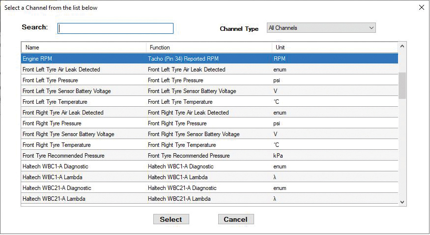
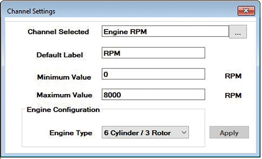
Connect this input to your current tachometer input wire. This wire can originate from a factory ECU, an ignition coil, or your engine wiring harness. To configure the RPM (TACHO IN) channel in the ICC software, select the tachometer on the main dash layout page. In the “Channel Settings” dialog box set your minimum and maximum RPM values (eg. 0-8000). Choose your engine configuration from the “Engine Type” drop-down menu and hit “Apply”.
Analogue Voltage Inputs (AVIP)
The Analogue Voltage Inputs on Haltech’s iC-7 can accept variable voltage levels from 0V to 5V.
The pre-calibrated inputs include air and coolant temperature, oil and fuel pressure, and fuel levels (volume) inputs. If your sensor is not listed in the “Sensors Connected” drop-down menu of the “Channel Settings”, you can use the “Custom” option and enter the calibration values manually.
Oil Pressure (AVIP 1)
The connector labeled “OIL PRESS” attaches directly to the Haltech oil pressure sensor. This connection is pre-terminated with a 3 pin Delphi connector.
Fuel Pressure (AVIP 2)
The connector labeled “FUEL PRESS” attaches directly to a Haltech fuel pressure sensor. This connection is pre-terminated with a 3 pin Delphi connector.
Coolant Temperature (AVIP 3)
The connector labeled “CTS” attaches directly to a Haltech engine coolant temperature sensor. This connection is pre-terminated with a DTM-2 connector.
Fuel Level (AVIP 4)
The flying lead connection labeled “FUEL LVL AVIP 4” is used to connect your existing fuel level sender to the iC-7 Display Dash. The harness also features a DTM-2 in-line connection for servicing.
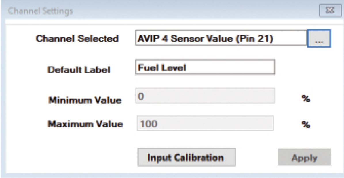
Once connected you can you calibrate your fuel level sender using Haltech’s ICC software.
To calibrate your fuel level sender go to “Dash Settings” then “Channel Settings” on the navigation menu. Choose “AVIP 4 Sensor Value”. Select “Input Calibration”.
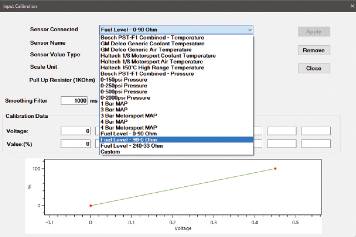
The sensor dialog box will show a list of pre-configured sensors including optional Ohm ranges for common sending units. If you have one of the pre-configured sensors, select it and click “Apply”.
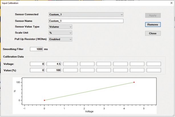
If your sensor type or Ohm range is not listed, you will need to input the “Custom” sensor type. With the fuel sender connected to your iC-7, connect a Voltmeter across your fuel sender gauge posts, and measure the minimum and maximum float height voltages.
Input those voltages to their corresponding value (0-100). For maximum accuracy measure all eight data points. Otherwise, leave them blank and allow the software to interpolate the values.
Oil and Fuel Pressure Configuration
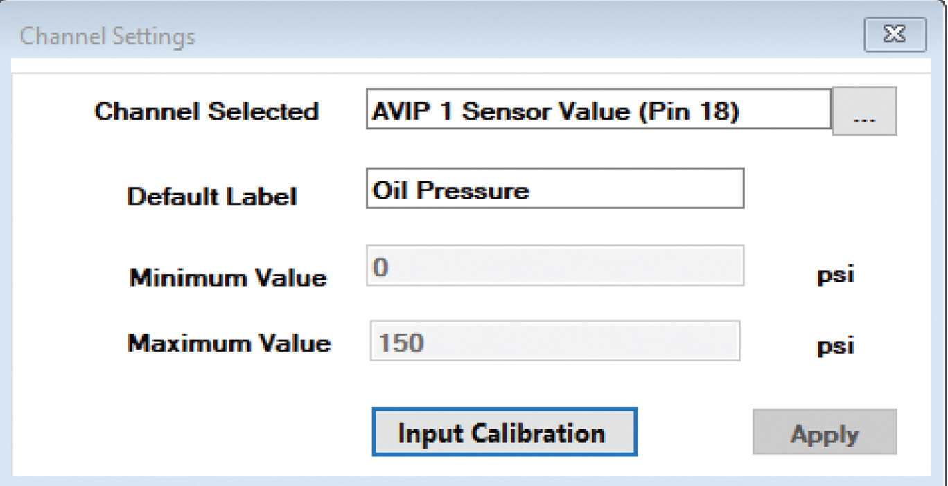
The AVIP1 and AVIP2 channels are already pre-configured for Haltech’s 0-150 PSI pressure sensors. They are labeled “Oil Pressure” and “Fuel Pressure” respectively. Follow the steps below if you need to change the sensor type or the display target of this channel:
1. Choose “Dash Settings” / “Channels” from the navigation menu.
2. Choose “AVIP1 Sensor Value”. You can change its default label “Oil Pressure” if required.
3. Select “Input Calibration”.
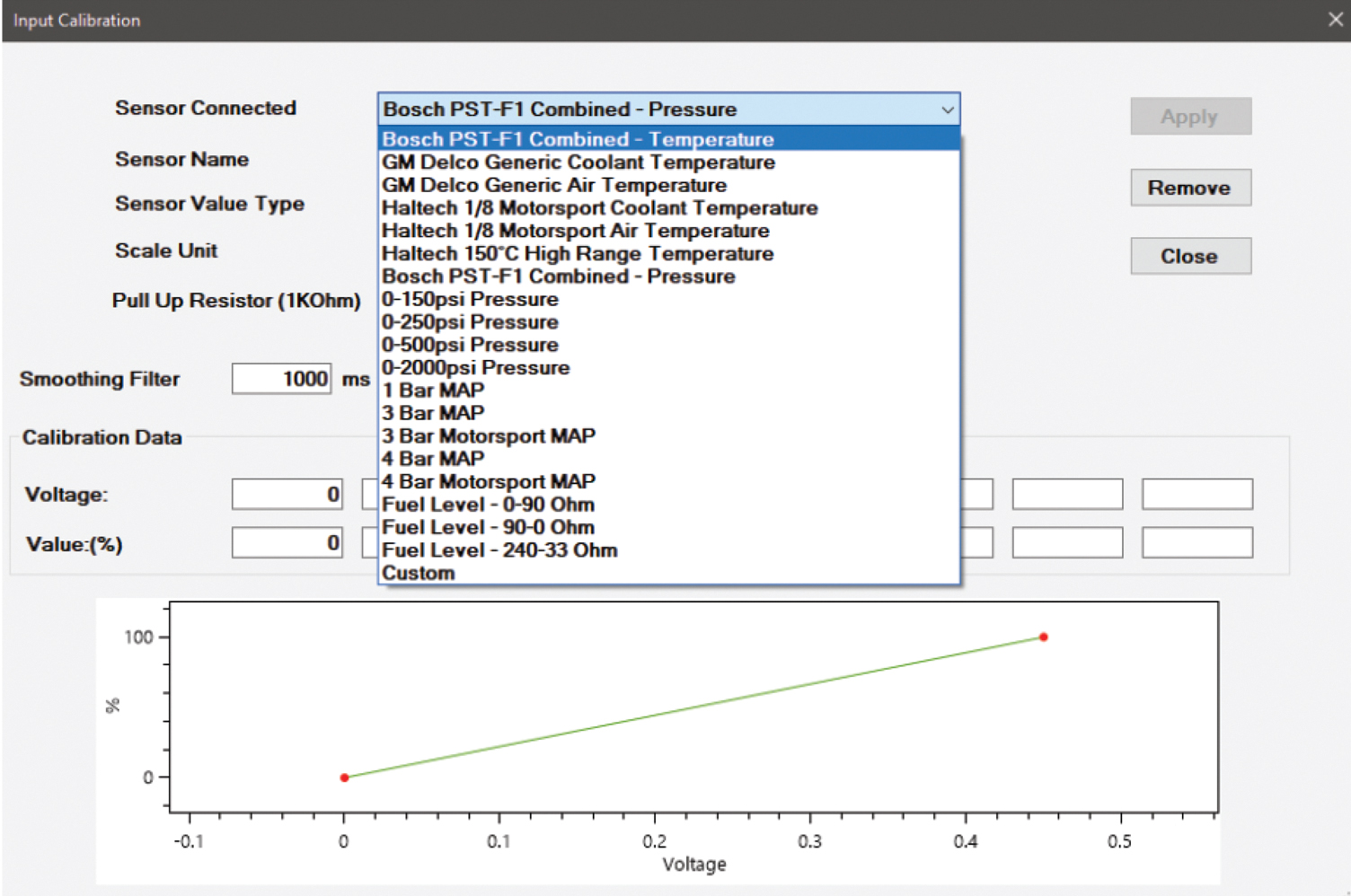
From this dialog menu, you can choose a different sensor type. You can also input a custom sensor type providing you know the voltage range and values for that sensor.
Most pressure transducers have a range of 0-5V, but this may vary and it is important to obtain the correct manufacturer’s sensor data prior to calibration.
Prefer watching to reading?
Well, you’re in luck, because we also have a video version of this article where you can see exactly how this install was done. While you’re there, subscribe to our YouTube channel for more tech tips, software walk-throughs and other car-related content.
Haltech iC-7 “Classic” Stand-Alone Kit
Part Number: HT-067014
Screen: Full colour 7” TFT display
Outside Dimensions: 217 x 122mm (8.5? x 4.8?)
Compatible with: Carbureted and mechanically injected cars.
All current Haltech ECUs via CAN.

What’s in the box:
• Haltech iC-7 Display Dash
• Semi-terminated stand-alone harness (HT-060300)
• iC-7 stand-alone sensor pack (HT-010001):
– 1 x coolant temp sensor 1/8 NPT (HT-010304)
– 1 x brass adaptor 1/8″NPTF to 3/8″NPT (HT-120000)
– 2 x 150PSI “TI” fuel/oil/wastegate pressure sensors (HT-010904)
• 34 Pin main connector harness
• DTM-4 to DTM-4 CAN extension cable
• USB to M5 right angle cable
• USB Cable
• Mounting Screws
• USB flash drive with iC-7 Software
• Quick Start Guide
• Haltech stickers and a fabric keyring tag
See all the iC-7 Mounting Options Available

