Category: Feature
What’s so special about the RB?
Nissan’s RB engine has long been a favourite of tuners and car enthusiasts around the world. But why? What makes this particular engine the favourite of so many?
The modern RB history story started with the launch of Nissan Skyline R32 GT-R in August of 1989.

After 16 years without a GT-R model, Nissan re-launched the Skyline GT-R as a showcase for, what was at the time, the pinnacle of performance technology.
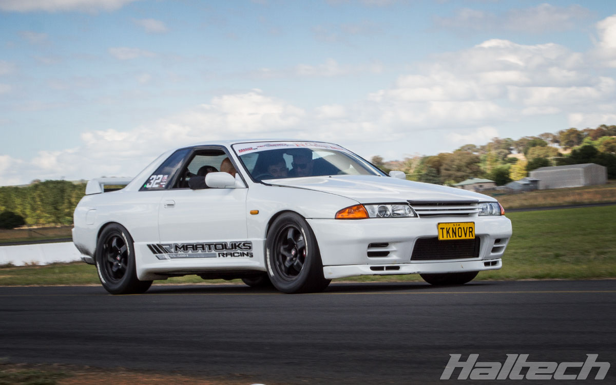
R32 Skyline
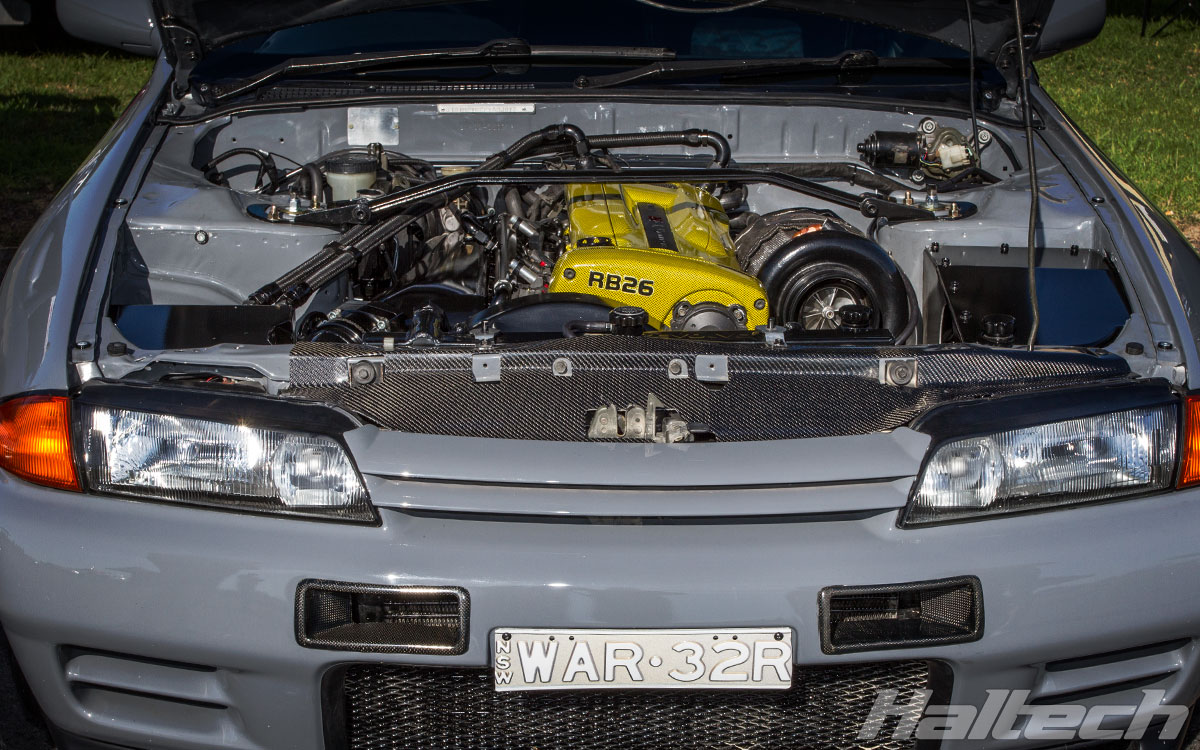
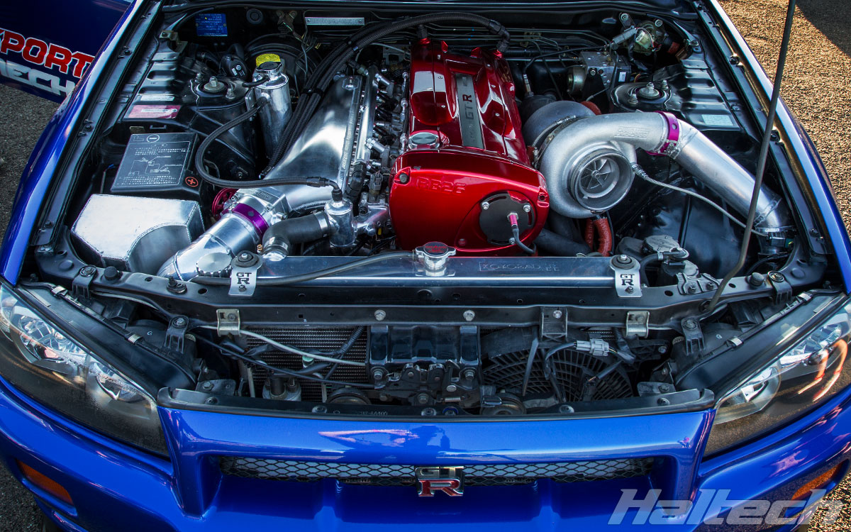
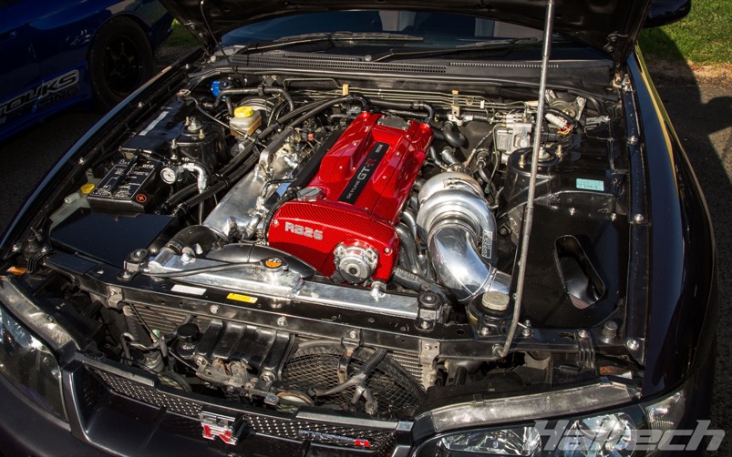
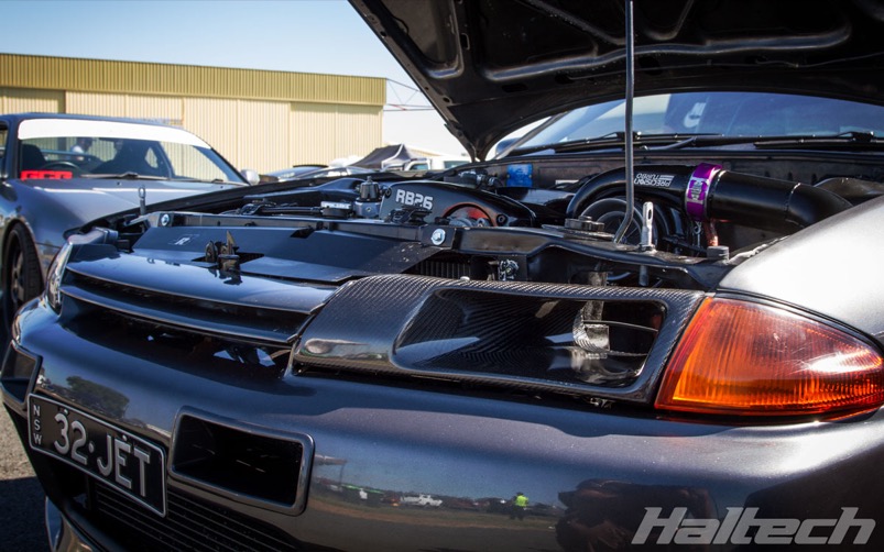
The R32 GT-R featured a Multilink suspension system, HICAS all-wheel steering and Nissans ATTESA all-wheel-drive system. But the clear highlight was the heart of the beast – the RB26DETT – a 2.6 litre turbocharged, inline 6 cylinder engine.
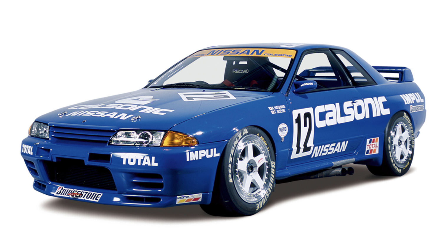
Off the showroom floor they made 276 horsepower with 260 lb-ft of torque. Zero to 60 mph took 5.6 seconds and they ran the quarter mile in 13.9 seconds.
The R32 race cars had great success in the FIA’s Group A series, both at home in Japan where the blue Calsonic-sponsored example has become a motoring icon, and in Australia the Aussie press nicknamed the fire-breathing monsters “Godzilla” when they dominated the local Ford and Holdens.
R33 Skyline
Next came the R33. It was first displayed at the 1993 Tokyo Motor Show, but its official launch wasn’t until January of 1995.
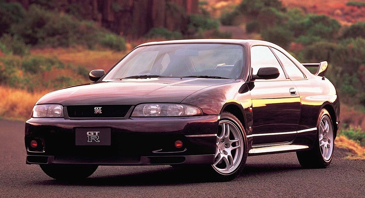
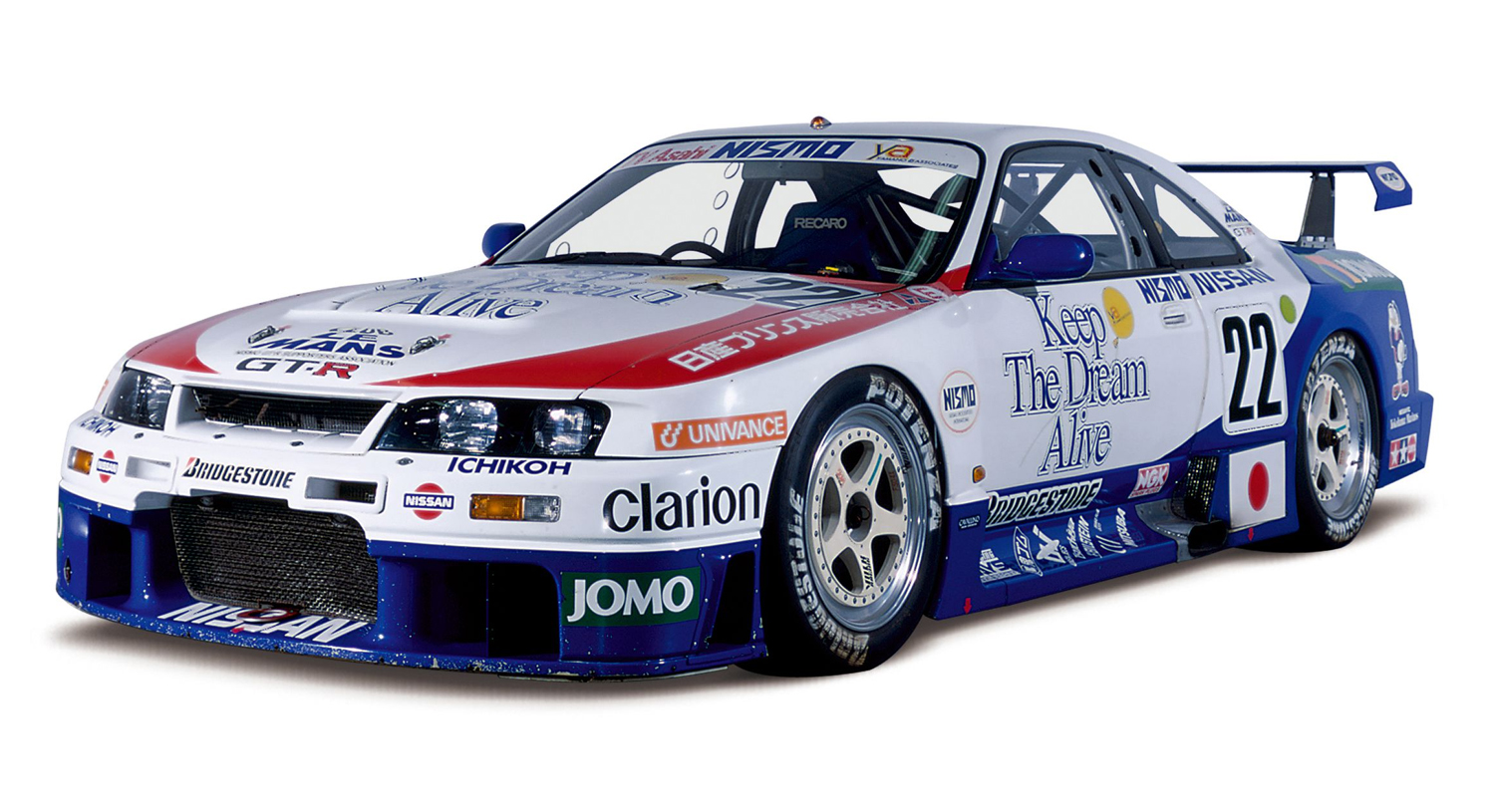
Still powered by the RB26DETT the R33 raced at Le Mans in the same year, finishing the gruelling event 10th overall and 5th in class. The R33 has gained a strong and loyal following of its own, in particular the limited edition Nismo 400R variant, with 400hp on tap and a limited run of just 50 cars.
R34 Skyline
Next came the R34, which would turn out to be the last GT-R powered by the RB26DETT. While horsepower was officially rated at 280 bhp, it would appear the car was more powerful than the manufacturer advertised with some examples making closer to around 330hp.
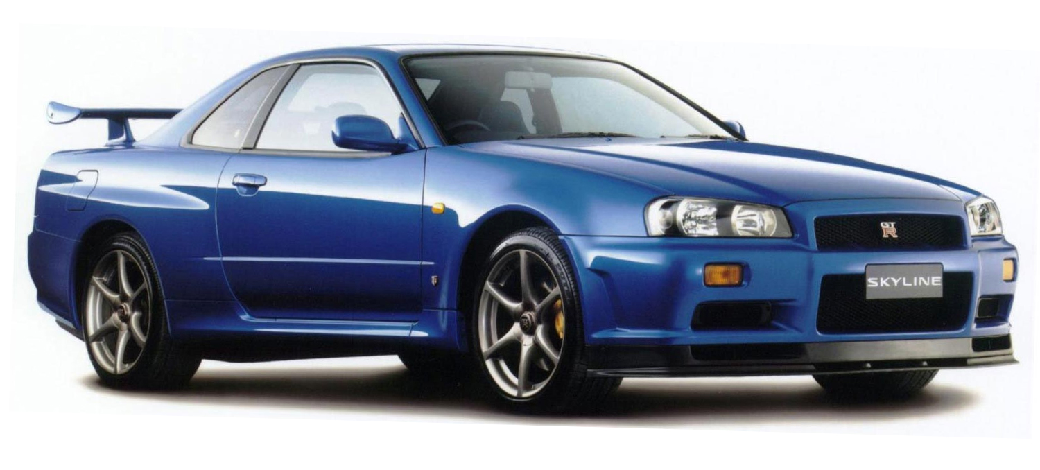
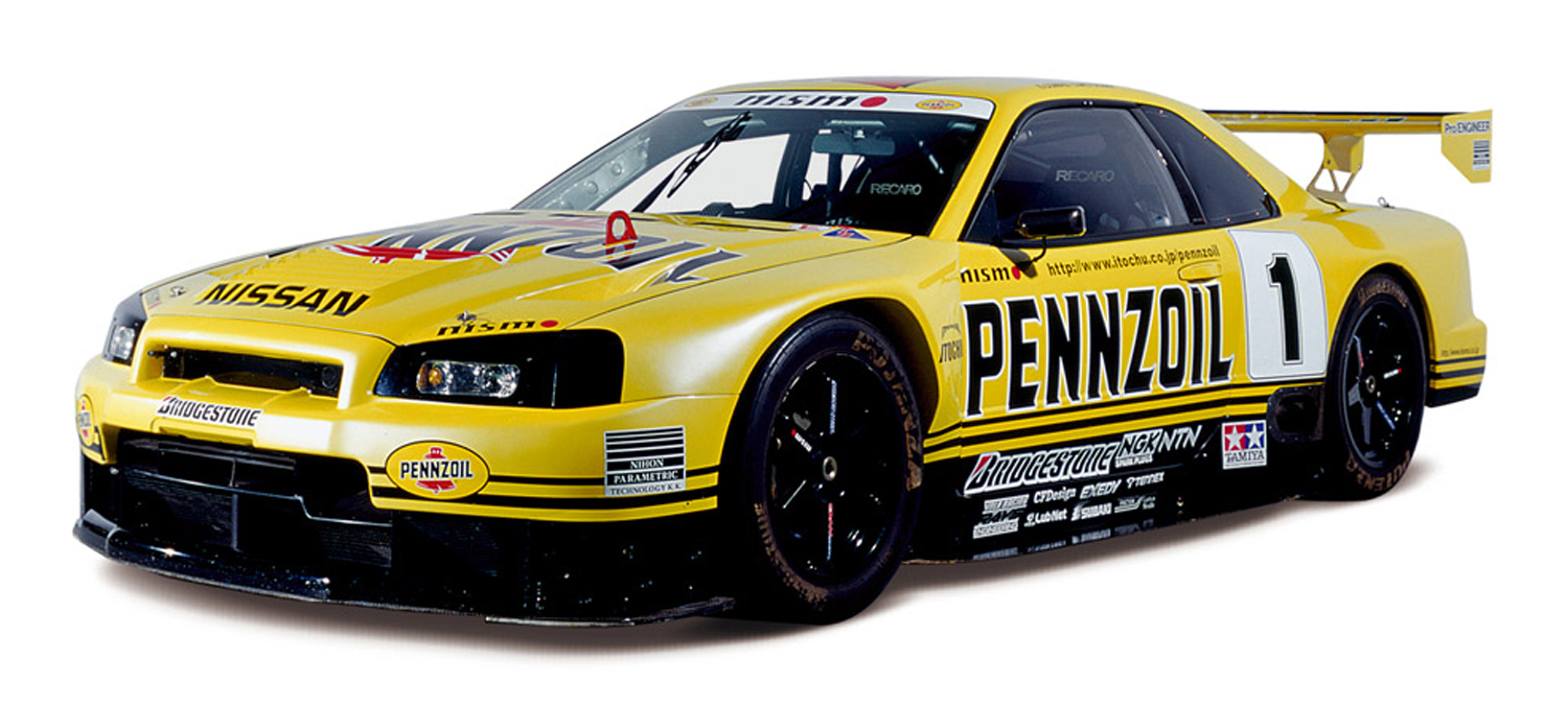
The R34 made a formidable race car, with the Pennzoil Nismo GT-R winning the Japanese Grand Touring Championship in 1999.
The R34 clearly benefitted from the racing and testing done with the two previous generations of GTRs. It still had the same advertised power, but turbo lag was reduced, it made more torque, and had a new 6-speed manual transmission which replaced the earlier series 5-speed.
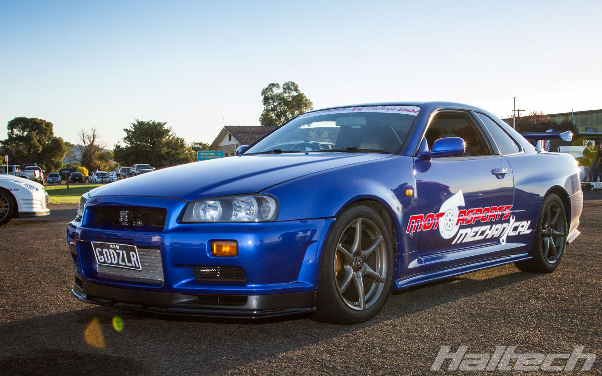
The body was also stiffer, the aerodynamics were improved, and several weight-saving measures were employed, including the use of a carbon fibre rear diffuser. The car was also shorter, as was the front overhang. The R34 GT-R was also featured in several of the “Fast and Furious” movies, giving American car enthusiasts a taste for the unobtainable Japanese Godzilla.
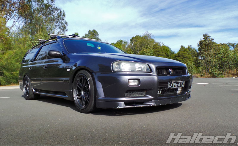
The GT-R wasn’t the only model to be blessed with RB Power. Much of the Skyline range from the R31 to R34 in both coupe and four-door body shapes, whether RWD or AWD, also benefited from the RB engine, as did a lot of the not-so-well-known Nissans including the Stageas, Laurels, Cefiros, and even the odd Patrol.
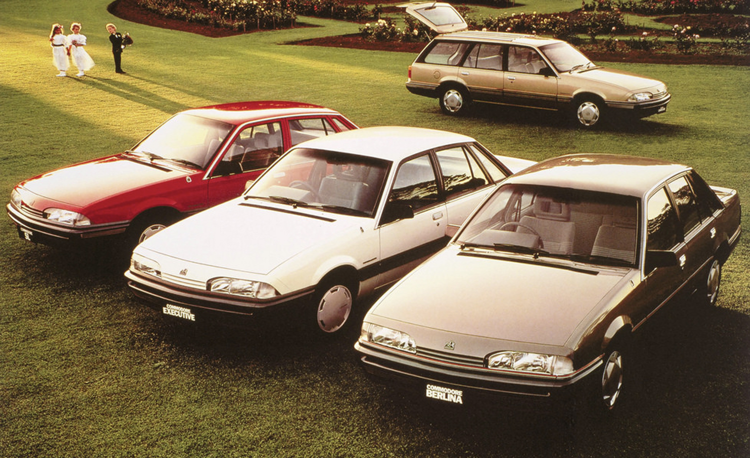
Of course, we can’t talk about RBs without mentioning the Holden VL Commodore. The VL was powered by Nissan’s single cam RB30, which in turbo form made 201 horsepower, giving it more grunt than the locally manufactured Holden V8s of the same era.

This made the VL turbo a favourite of both the Police highway patrol and car enthusiasts alike.
Should you get one?
The answer is most certainly yes! This is one of, if not THE most famous Japanese “Muscle” engine of all time. They look right at home in a wide range of Chassis like the Silvias and Skylines and especially in older Datsun bodies like 240z or 260z.
Which variant should you use?
It all depends on what you can get your hands on and what you are going to do with it. RB20, RB25, RB26 and RB30 are all good engines and all have that great RB sound! There’s huge aftermarket support for the RB series and with most parts like cranks, rods, pistons, camshafts, stud kits and gaskets available off the shelf.
All you have to decide is whether you want one cam or two, one throttle or six, 2L, 2.5L, 2.6L or 3.0L and whether you wanna gear it towards a smaller street turbo or a giant dyno killing monster.
And that’s the real beauty of the RB – so many uses and so many choices really do make this one of the great ultimate all rounders.
Tuning Options
When it comes to RBs Haltech has been one of the first aftermarket ECU manufacturers to provide engine management solutions for these popular engines.
Haltech-powered RBs have been successful in various types of motorsport, from drag racing, drift and time attack and circuit racing.
If you’re after an ECU for your RB-powered vehicle you’ll have plenty to choose from.
Use the guide below to choose the right Haltech ECU for your RB application.
Race Applications
Elite 2500 and Nexus R with custom wiring will suit all RB30/RB20DET/RB25DET/RB26DETT applications.
Model-specific Plug’n’Play Solutions
Nissan R31 (RB30)
Products available: Terminated Engine Harnesses Kits.
Nissan R32 GTS-T (RB20DET)
Products available: Platinum Pro Plug-in ECUs and Elite Plug’n’Play Adaptor Kits.
Nissan R32 GT-R (RB26DETT)
Products available: Platinum Pro Plug-in ECUs and Elite Plug’n’Play Adaptor Kits.
Nissan R33 GTS-T (RB25DET)
Products available: Platinum Pro Plug-in ECUs and Elite Plug’n’Play Adaptor Kits.
Nissan R33 GT-R (RB26DETT)
Products available: Platinum Pro Plug-in ECUs and Elite Plug’n’Play Adaptor Kits.
Nissan R34 GT-T (RB25DET)
Products available: Platinum Pro Plug-in ECUs and Elite Plug’n’Play Adaptor Kits.
Nissan R34 GT-R (RB26DETT)
Products available: Platinum Pro Plug-in ECUs and Elite Plug’n’Play Adaptor Kits.
What’s So Special About Honda’s K-series
Honda’s contribution to motorsport and the JDM performance scene is unquestionable and today we’re going to take a closer look at what is arguably the most popular “modified” Honda engine – the K-series.
Once upon a time in Japan….
Let’s start with a little history about Honda itself. Honda’s founder, Soichiro Honda actually started out making piston rings for Toyota! He then moved into motorcycles in the late 1940’s which were assembled in a wooden shack.

The bikes were followed by a small pick-up truck in the early 60’s and the first ever Honda production car – the S500 sports coupe, followed in October 1963.

It turns out Honda-san was a big fan of motorsport. In 1954 he decided Honda Motorcycles would race in the Isle of Man TT. It took them five years to develop the motorcycles, and on debut in 1956 Honda won the manufacturer’s team award.

In 1961, with legend Mike Hailwood on board, they won two of the TT races. Not only that, they also won the 250cc and 125cc titles in the World Motorcycle Grand Prix Season.

With that success under his belt, in 1962 Honda decided to aim for F1. A few more years of development and Honda was on the podium, with a win at the 1956 Mexican Grand Prix. Honda has since been racing in F1 and supplying engines on and off throughout the years right through to the present day.

The highlight of which is probably Honda’s partnership with McLaren in the late 80’s and early 90’s, and the relationship forged with late, great Ayrton Senna who was instrumental in the development of the original Honda NSX – the most advanced production sports cars of its time.

It would take a whole separate article to cover Honda’s involvement in the Japanese Super GT Series, British Touring Car Championship, World Touring Car Championship, Indy Car, Le Mans, and just about every type of Motorcycle racing but what it all boils down to is that Honda has done a HUGE amount of motorsport, and that motorsport experience has led to Honda’s power plants not only being very efficient, but also very well engineered and extremely reliable.
Which brings us to the subject of this article – the Honda K Series.
There’s something special about the K…
The K-series is, without a question the favorite swap for front wheel drive Hondas. Fans of golden era 90’s Hondas have been binning their D, F and even B series engines in favor of the K-series since they hit the scene in the early 2000’s.

The Honda K-series was first offered in 2001 in the hot hatch Type-R trims of the Civic and Integra and is still offered today in DI form on several Honda/Acura models. Nearly a 20-year life span means that there are plenty of variants of this engine to choose from.

The most popular models for swaps and performance applications are the early K20 engines from the 2001 through 2006 EP3 Civic and DC5 Integra and the K24 engines from the 2002 through 2008 Honda Accord and Acura TSX.

Often touted as the best performing package is a hybrid combination of both with the high-flowing K20 head and the larger displacement K24 bottom-end.

In recent years the rear wheel drive K-swap market has exploded with several aftermarket manufacturers producing rear wheel drive gearbox adapters, conversion parts and even full kits to swap the K-series into the Honda S2000, Mazda RX-7, Mazda MX-5 and even Nissan S and R chassis cars.

With pieces and parts from these manufacturers and a little fabrication knowledge, it is possible to put Honda’s venerable 4 cylinder into virtually any chassis you prefer.

Within this segment, the K24 from the 2009-2014 Accord/TSX is also extremely popular due to its plentiful supply, low cost and advantageous exhaust packaging with the exhaust manifold runners being cast right into the cylinder head.
Made for motorsports
The Honda K-series engine has enjoyed continued success in motorsports from Drag Racing to Time Attack, wheel-to-wheel circuit racing and even European Autocross.

In drag racing, the K-series has a torque advantage over the older Honda designs and frequently rulesets allow advantages to the older B and H series engine to even the playing field.

The fastest All-motor K-series racers are in the 8’s now and the turbo cars are pushing deep in the 7’s. These cars are getting so fast that racers are now employing AWD conversions to try and go even faster.

Time Attack racers like James Houghton and Rob Nguyen rely on high horsepower turbo K-series to set records on tracks all across the world.


A de-tuned K-series is the winning formula in power-to-weight racing series such as GridLife’s Touring Cup where over half of the top contenders are K-series equipped.
In European autocross, racers like Marcus Thomas use a 2.7 liter stroked version of the K-series to propel his buggy to numerous wins and championships.
Things to watch out for
Honda’s legendary reliability carries over to the K-series. With few common flaws, a standard compression check is just about all that’s needed to ensure a healthy engine is chosen for your project.
If you have the time or resources to inspect an engine before purchase, it’s worth it to remove the valve cover and inspect the condition of the valvetrain and camshafts.
What you’re looking for here is oil sludge build-up or heavy oil varnishing. This could be evidence of a lack of routine maintenance and may result in premature camshaft or bearing wear.
Haltech Tuning options
Haltech Elite ECUs support the factory trigger patterns for all variants of the K20A, K24A, K20Z and K24Z. Additionally all forms of i-VTEC are supported including single or dual cam control and electronic lift control. Your ECU choice depends upon the features of your specific engine.
Engines with variable intake cam and without drive-by-wire in non-motorsports applications might opt for an Elite 1000 but most applications would benefit from the added 4D tuning flexibility of the Elite 1500. Applications with drive-by-wire or dual cam control applications will require the Elite 1500.

For early model K20 and K24 engines with harnesses that suit EP3 Civic or DC5 Integra/RSX pinouts, Haltech offers PRO Plugin ECUs and Plug’n’Play Adapters to suit the Elite 1000 and 1500.
Engine overview
At first glance, Honda’s K series doesn’t appear to be worth any high-performance merit. Just another pedestrian 4-cylinder mill, known for excellent gas mileage. From the factory it’s a bit boring having no turbo and a modest redline.

What’s not immediately evident is the platform’s potential. A robust all-aluminum, DOHC engine outfitted with a coil on plug ignition system, roller rockers, forged crankshaft, cast iron sleeves and Honda’s venerable i-VTEC which includes electronic lift control and variable timing control on one or both cams.

Simple and ingenious in design, Honda’s electronic lift control allows one single camshaft to have, effectively, two profiles.

The low profile provides miserly fuel economy in cruising situations and a more aggressive high cam profile providing greater airflow and top-end performance.

New for a Honda 4-cylinder in 2001, the K-series had Variable Timing Control via ECU controlled hydraulically adjustable cam gears.
This complement of technologies that allowed both economy and performance was dubbed i-VTEC as the next generation of Honda’s revered VTEC system.

K-series tuners have expanded the horsepower output of these engines by outfitting turbochargers, superchargers and even nitrous.

Completely stock long blocks are known to hold upwards of 400 horsepower, swap out the pistons/rods and the stock crank and sleeves can handle 700hp. Fully built engines can achieve impressive horsepower numbers cresting over the four digit mark.

Useful Links:
Plug’n’Play Adaptor for Integra DC5/Acura RSX (05-06) Overview
Plug’n’Play Adaptor for Civic EP3 (02-05), Integra DC5/Acura RSX (02-04)
Plug’n’Play Adaptor for S2000 Overview
All Honda Plug’n’Play ECUs and Adaptors
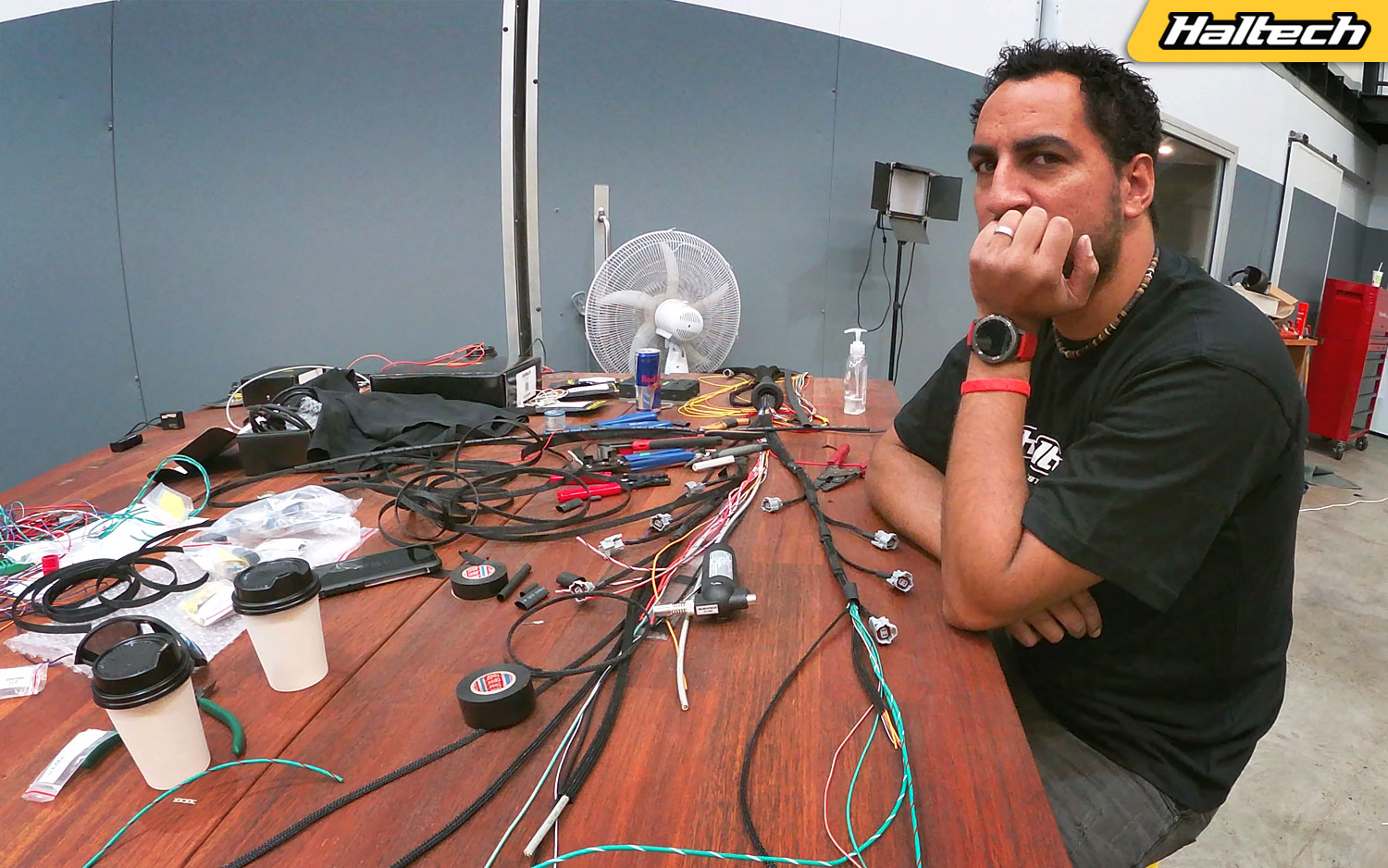
Dave’s Wiring Vlog
Everyone tackles self-isolation differently. Dave’s way was to put up a makeshift isolation booth in the corner of Haltech garage and wire a car!
We figured it was a great opportunity to vlog the entire process. Of course, given the recommended social distancing rules he would have to do it all himself… It took a bit of convincing but Dave finally agreed. Welcome to Dave’s Wiring Vlog – in all its raw beauty!
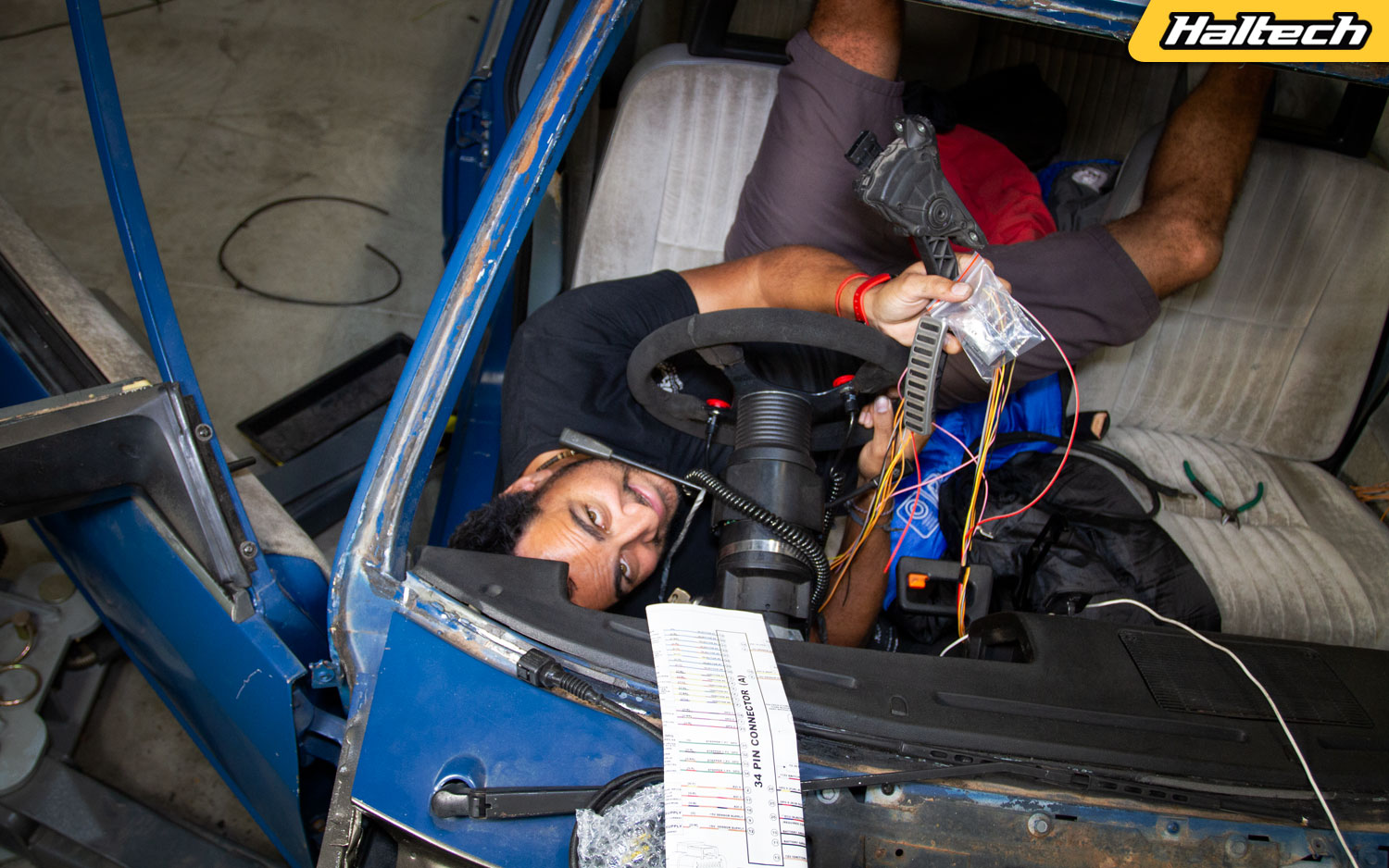
Episode 1
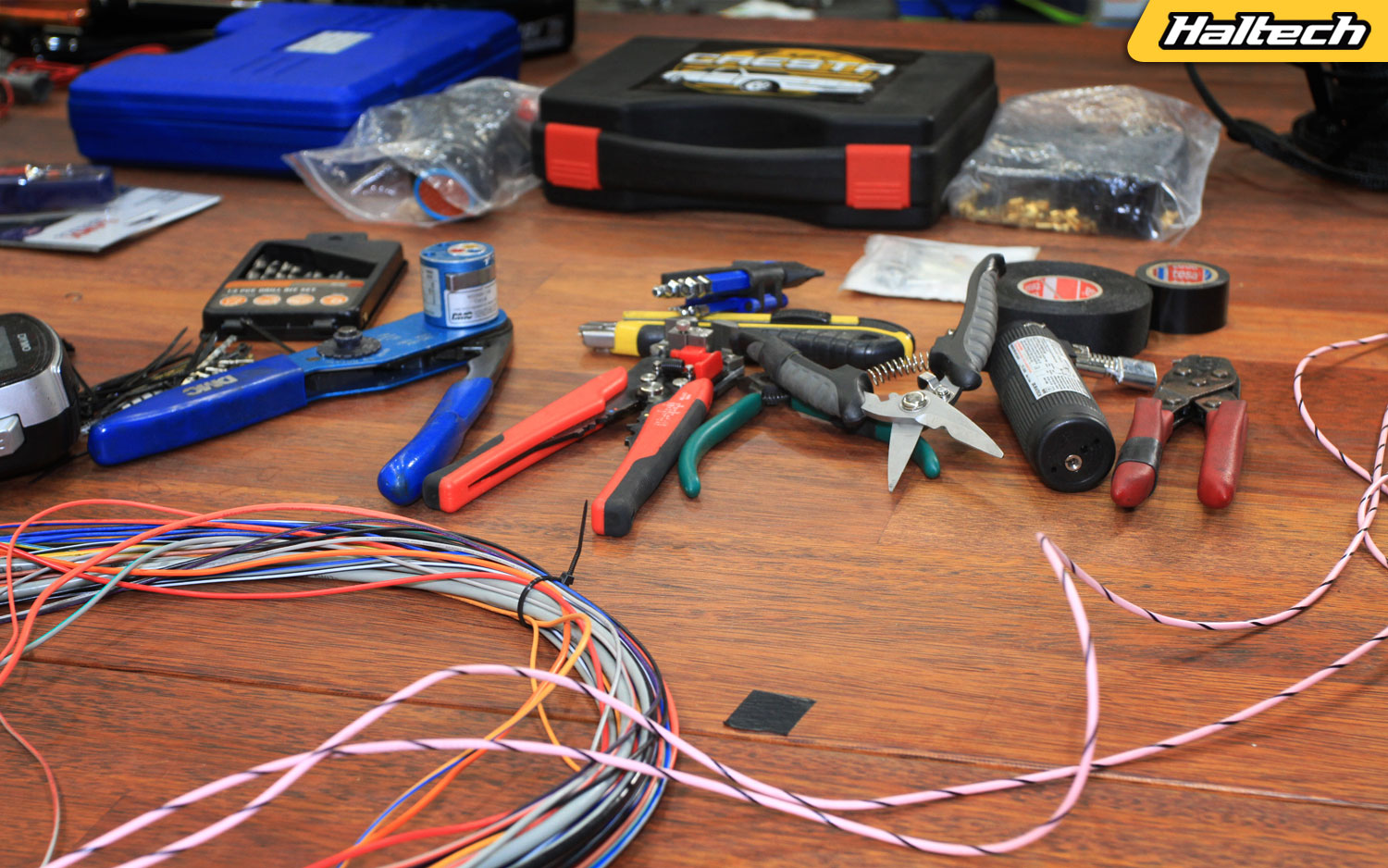
In the first episode Dave introduces the car/engine he’s going to be wiring, talks us through all the tools he’s going to be using and then starts the harness prep by separating all the different wire groups.
Episode 2
It’s time to figure out what each wire is supposed to do. Dave prints out an input/output report diagram from the ESP software and assigns each wire in the harness to its rightful place on the diagram. This step is super important as this is where we decide what function each wire in the harness will control. Dave then puts the wire in groups based on their functions and their location in the car.
Episode 3
Haltech’s Premium Wiring Harness includes an integrated fuse/relay box. In this episode, Dave sorts out all the fuses and relays and adds a couple to deal with a boot-mounted thermofan.
Episode 4
It’s time to add a CAN loom into the harness and Dave shows us a quick and easy way of doing it. More hacks and shortcuts in this massive episode as Dave splices in some extra long wires for the rear mounted fuel pump, trans fan and power steering and shows us his braiding technique.
Episode 5
We’re up to our first “point of no return” and that is drilling a hole in the firewall! Dave does a trial fitting of the harness inside the engine bay and lays out all the engine wiring. There’s a lot of pushing, pulling, measuring, checking and cutting going on before the harness is taken out again to be completed for the final install.
Episode 6
Measure twice – cut once! The wiring comes out of the car again for final grouping, cutting, braiding and terminating. Both injector looms (one for each bank) get completed and terminated with connectors. The harness is now ready for the final install.
Episode 7
With the harness back in the car Dave starts with the car up on the hoist and then works his way into the engine bay where he wires all injectors and coils followed by a whole bunch of sensors; cam, crank, flex, knock, thermo fan, air temp, fuel pressure along with the dbw throttle body, alternator, battery. Dave also explains the subtle differences between the pull-to-seat and push-to-seat connectors and figures out the best place to mount the wideband controller box.
Episode 8
We’re on the home stretch! Dave’s inside the cabin now and wires up the DBW pedal then moves onto the ignition switch and the bump & creep buttons. While still in the cabin Dave also crimps the coil wires and completes the ignition loom. Back in the engine bay Dave repositions the factory headlights/blinkers loom so it’s nicely tucked out of the way.
Episode 9
It’s the final day! Dave tidies up all the loose ends under the car and shows how to use a Power Probe (it’s quite handy!). Moving into the car the iC-7 Dash find its rightful place in a custom-made cluster.
Dave then gets down and dirty on the ignition switch. Moving to the rear of the car Dave wires up the power steering pump and the fuel pumps as well as the transmission cooler fan. Back in the cabin – it’s crunch time, with the ECU connected will it all work when Dave turns the key? We’re about to find out….
The finished project
So, how did the car end up looking? A few months later we got the car back to do a quick follow up video and answer some of the questions posted during the wiring process.
Tools and Products Used
Elite 2500 + Premium Wiring Harness: https://www.haltech.com/product/ht-151304-elite-2500/
Dual Crimper Set: https://www.haltech.com/product/ht-070300-dual-crimper-set/
Plugs, pins and wires: https://www.haltech.com/product-category/plugs-pins-and-wiring-products/
Wideband Controller Kit: https://www.haltech.com/product-category/can-expansion-products/can-wideband-controllers/
EFI Hardware: https://www.efihardware.com/
Power Probe: https://www.powerprobe.com/
RS Components: https://au.rs-online.com/web/p/crimp-butt-splice-terminals/7187561/
Tesa Tape: https://www.tesa.com/en-au/industry/tesa-51608.html
Connector-Tech ALS: https://www.connector-techals.com.au/
3D Racing solutions: https://3dracingsolutions.com/collections/dash-clusters
Want to learn Automotive Wiring?
High Performance Academy Pro Wiring Courses: Https://www.hpacademy.com/courses/professional-motorsport-wiring-harness-construction/
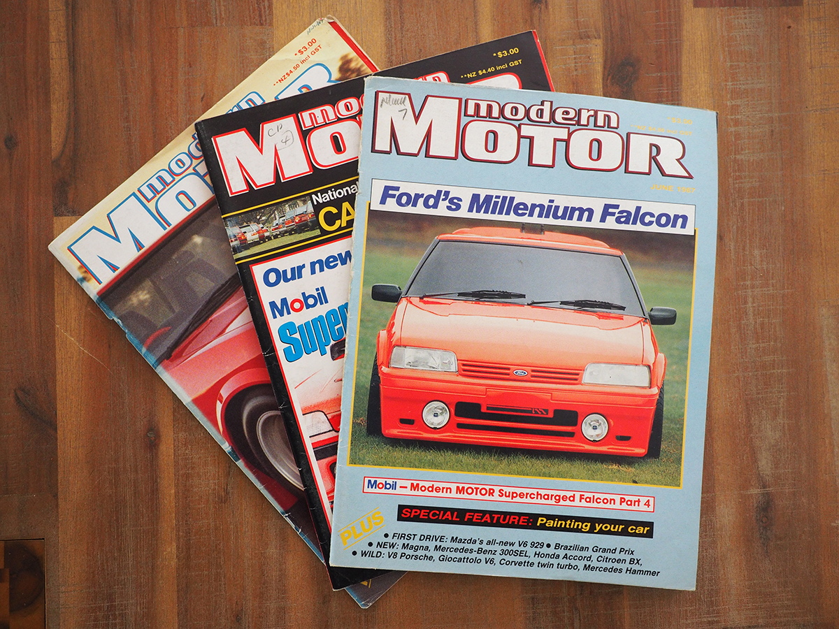
A Trip Down Memory Lane – Part 3
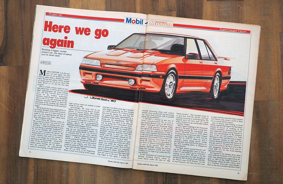
Welcome to the final installment of our trip down memory lane – A peek into the pages of Modern Motor Magazine and the project car that started the ball rolling for Haltech. If you missed parts one and two, you can catch up here and here.
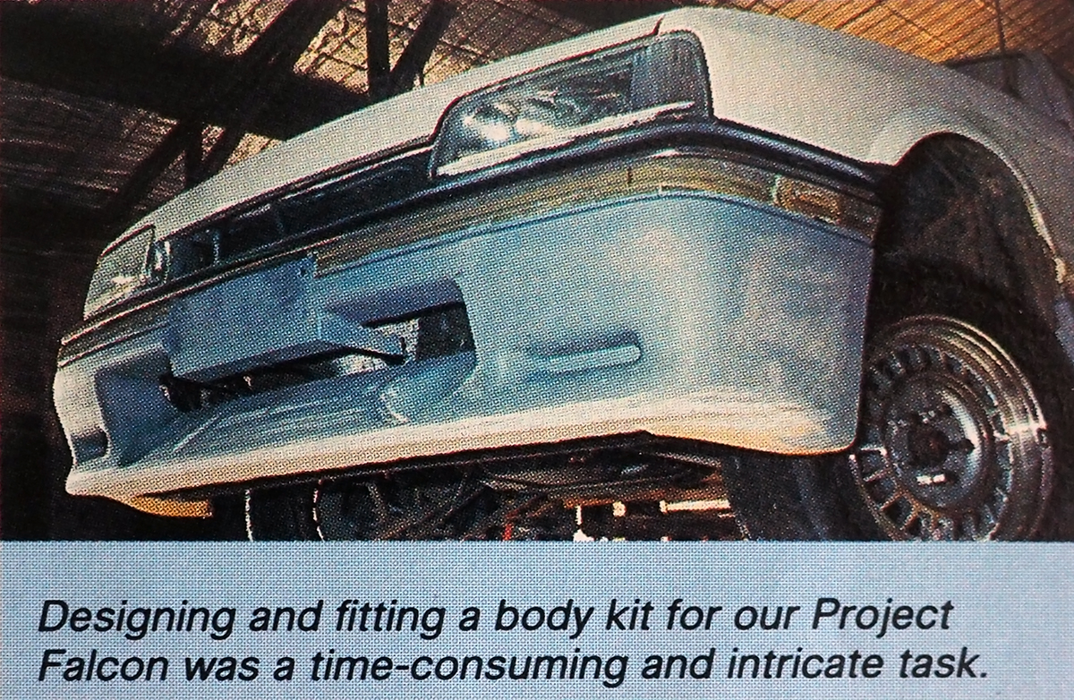
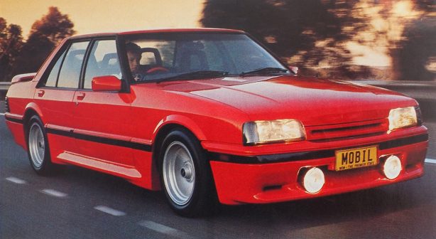
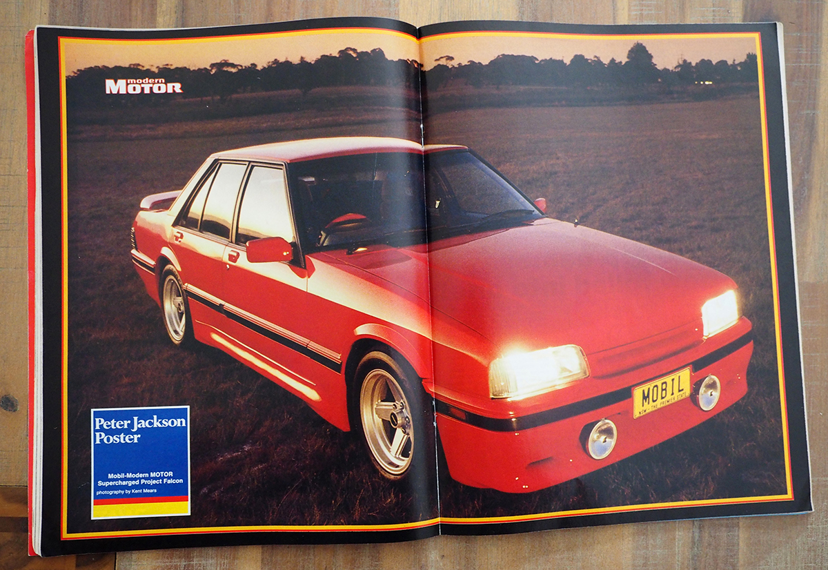
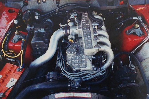
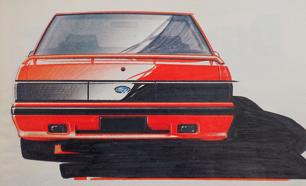
By the time November 1987 rolled around the Mobil Modern Motor Supercharged Falcon was ready to hit the streets. Wrapped in a new body kit, penned by ex-Holden stylist John Learson, it certainly looked fast. It wasn’t all show and no, go, however – The XF had the muscle to match the make-over.
The Sprintex Supercharged straight-six made 1980s V8-style grunt with 180kw at 4000rpm, and 435Nm at 2500rpm. It accelerated to 100km/h in 8.65 seconds and did the standing 400m (near enough to a quarter mile) in 15.56 seconds at 144km/h (89.5mph).
One thing it wasn’t though, was cheap. Including the purchase price of the original vehicle, the estimated bills came in at around $53,000 – That’s $8,000 more expensive than a brand new Holden HDT Group Three Commodore was!
Below is an excerpt from Part Four of the Project Car build, as published in the June 1987 Issue of Modern Motor, this breakout was written by Haltech founder, Steven Mitchell himself. Republished with permission from ARE Media.
Computer Program
THE Ford EEC4 engine management system was first introduced in America in 1983 on the Escort 1.6 litre and turbocharged 2.3 litre engines. Later it saw service on all Ford, Mercury and Lincoln engines with fuel injection and on the carburettored engine used in Mustangs, Capris, LTDs and Marquis’.
In Australia, the system is used with a vane airflow meter on the Falcon and with a manifold pressure sensor on the F100 range. When these systems first appeared in Australia I successfully contracted to several Ford dealers to diagnose electronic faults which they were having trouble with at the time and as a result I am very familiar with the EEC4 system.
There are three distinct problems to be solved to allow the Mobil-Modern MOTOR Falcon to be successfully supercharged:
1. The basic fuel delivery curve must be accurately extended to cope with the increased airflow.
2. The ignition timing must be regraphed for maximum efficiency without knocking.
3. The constricting effect of the standard vane air flow meter has to be removed.
The brain of the EEC4 system is the Electronic Control Assembly (ECA). This microcomputer acquires information from engine and transmission sensors and selects a strategy with which to control fuel delivery, ignition timing, idle speed and emission controls.
We considered designing an ECA to suit our requirements but this produced two problems. The standard Falcon fuel injectors can only flow an extra 10 per cent more fuel than the standard vehicle uses and would have to be replaced with larger injectors. Larger injector capacity implies lower accuracy in fuel delivery for the same injector control circuitry. The ECA is a complex device and much effort would go into simply duplicating the low end performance the standard Ford unit provides. We do not wish to re-invent the wheel.
This led us to the more standard approach of adding a second fuel injection system to take up when the Ford’s own system runs out of steam. Once. the supercharged airflow exceeds the maximum airflow reached by a standard engine, the pivoting vane airflow meter will be wide open and the standard management system will continue to inject the same quantity of fuel per injection regardless of increasing airflows.
The additional fuel injection system starts to function at the point where the standard system tapers off so as to allow the fuel delivery curve to smoothly continue. This additional system will measure inlet manifold vacuum rather than airflow. Manifold pressure related to the volume of air flowed by the velocity ratio of the inlet manifold, is a constant for a given manifold design. This systern will inject the additional fuel by means of two injectors positioned downstream of the supercharger.
The basic fuel delivery curve used by this additional system will be stored digitally in a “read only memory”. With the car on the vane dynamometer and the necessary gas/ignition analysers connected, this fuel delivery curve will be set by means of an external computer capable of changing the curve with the vehicle running.
This basic fuel delivery will then be multiplied to correct for variations in engine temperature or inlet air temperature. Once a curve is fixed, a ROM chip is “burnt-in” so that it can not be tampered with while in service on the vehicle.
The ignition timing is set by the ECA. The distributor sends the ECA a stream of pulses (profile ignition pulses) synchronised to when each piston reaches IO degrees before top dead centre. Accurately knowing where 10 degrees before top dead centre is, the ECA times out the correct position to fire the electronic thick film ignition module and hence determines the ignition timing.
We have rotated the distributor so that the profile ignition pulses occur 20 degrees before top dead centre. We have then placed an electronic delay between these profile ignition pulses and the ECA. If we delay the PIP pulses by 10 degrees then the ECA will see them occur at the normal 10 degrees before top dead centre, (i.e. 20 degrees static timing -10 degrees of delay equals 10 degrees static timing).
If we delay the PIP pulses by more or less than 10 degrees then we have effectively retarded/advanced the ignition timing. This new ignition timing map is stored in another “read only memory” and will be set in much the same way as the fuel delivery curve once on the dyno.
The standard management system is fitted with an anti-knock sensor attached to one of the front head bolts. Once this senses engine predetonation the ECA alters the ignition timing by a fixed amount to eliminate the knock. This is done partially at the expense of engine performance. These sensors may detect a “phantom” knock which can cause an unexplained flat spot on acceleration as the ECA tries to eliminate non-existent predetonation. We have disconnected this knock sensor and have in mind several alternatives to deal with the problem of predetonation.
And that brings us to the end of our three-part journey! Unfortunately, we don’t have any information as to what fate befell the Mobil Modern Motor Supercharged Falcon once the magazine feature came to a close, but we like to think it is sitting in a shed somewhere out there in the Aussie outback, just waiting to be rediscovered and brought back to life.
A Trip Down Memory Lane – Part 2
Welcome to part two of our trip down memory lane – A peek into the pages of Modern Motor Magazine and the project car that started the ball rolling for Haltech. If you missed part one, you can catch up here.
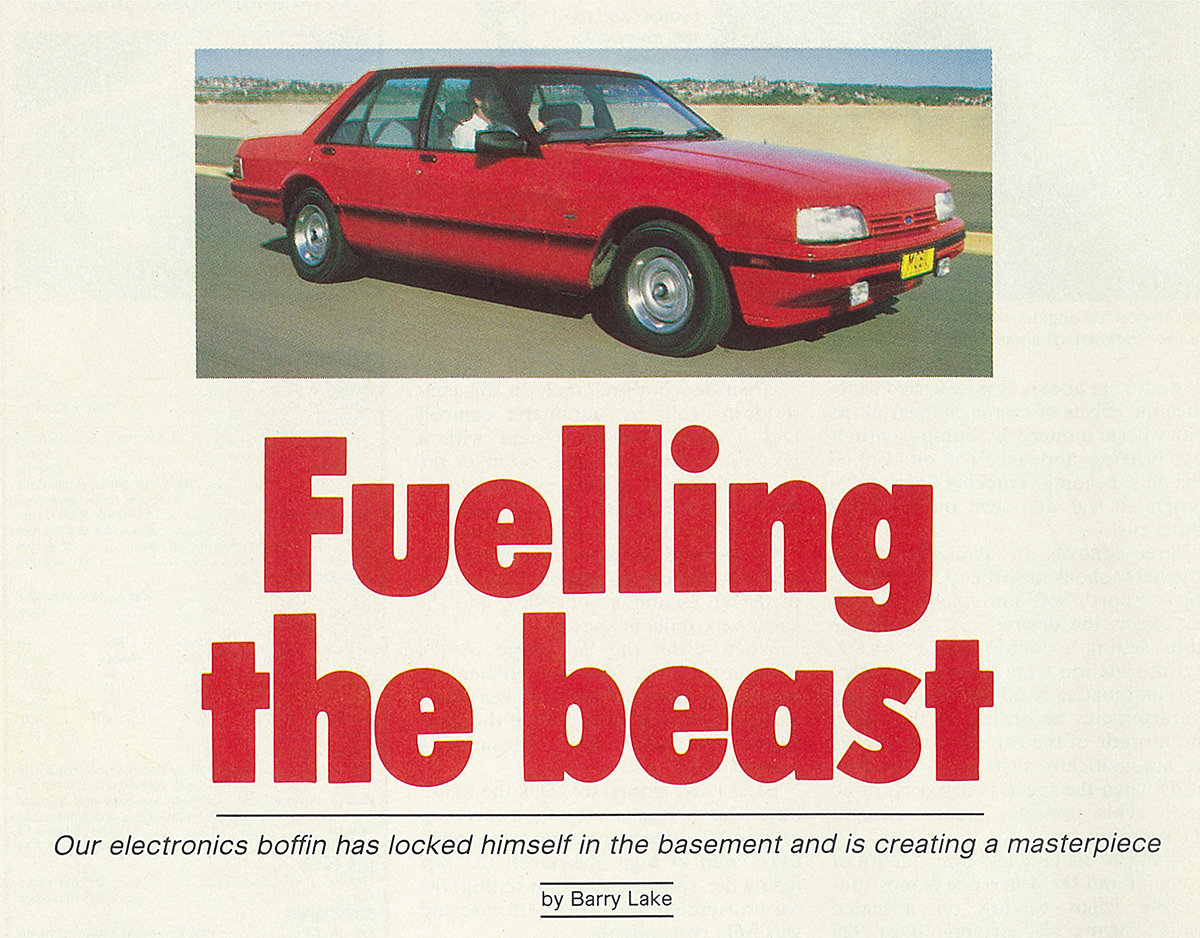
In this instalment Modern Motor Editor, Barry Lake takes us further down the 1980s fuel injection rabbit hole, the challenges that the project car team faced with supplying fuel to the newly supercharged engine, and the custom solution they came up with.
Spoiler Alert: While Haltech is now best known for complete stand-alone engine management systems, Steve’s invention was actually a separate piggy-back fuel injection set-up.
Read this excerpt from Part Four of the Project Car build, as published in the June 1987 Issue of Modern Motor, to learn more. Republished with permission from ARE Media.
While our US experts advised us to fit larger injectors for each cylinder and to fit their complete replacement computer to control the fuel and ignition management – this being the obvious way for a manufacturer to go when developing a new car – Steve took a different route, but one which better suited our needs. He decided to stay with the Ford EEC4 (“Eek-four”) engine management system as it would still happily cope with most daily driving conditions asked of our car when full performance and supercharger boost are not required.
To this system, Steve has added a second fuel injection system which comes on-stream when the EEC4 has reached its full output and can no longer cope with the engine’s extra needs.
This is where Ed and Steve had to work together, Ed selecting new components which could cope with the engine’s much higher output potential, and Steve producing an electronic management system to suit.
Ed’s calculations showed that the biggest restricting factor of the standard system is the vane airflow meter. This is the air intake for the engine, produced by Bosch and commonly used on many makes of electronically injected cars all over the world. It contains the air flap valve which swings back as the air passing through it (governed by the throttle opening) increases, operating an electronic potentiometer which sends a signal to the computer to tell it how much air is passing through. There is also an air temperature sensor which tells the computer the density of the air (air and fuel having to be mixed as a ratio of weight rather than volume for the most efficient mix).
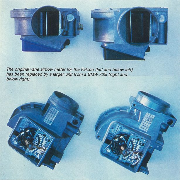
By Ed’s calculations, the standard vane meter was barely adequate for the standard car’s needs, certainly nowhere near coping with ours. So he selected an easily-tracked-down larger version of the same thing, also by Bosch, from the BMW 635/735 series cars, which is actually larger than those cars’ needs, but large enough for ours.
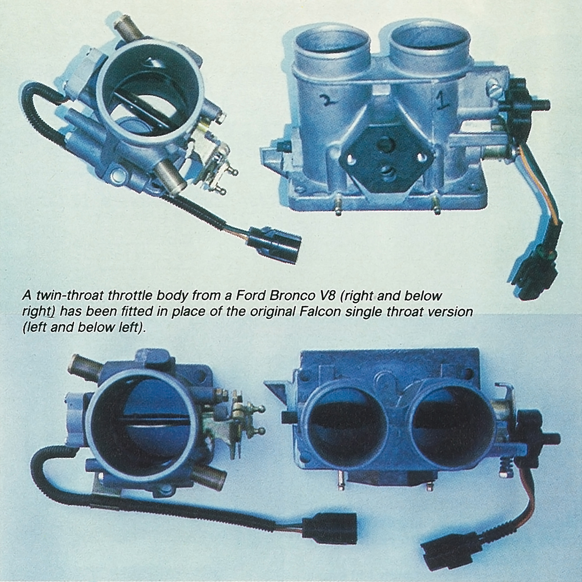
The injection system’s throttle body was not such a restriction to the standard car but was still not big enough for our project. Ed’s investigations showed that the dual-butterfly throttle body from a Ford Bronco 4wd’s 5.8 litre V8 was just right.
We had a stroke of luck here because, with our projected overall costs already climbing in the usual fashion, a $500-odd part can become yet another accounting headache. But the PR department of the Ford Motor Company, whose engineers had already been helpful with advice from the start, found a little-used and no longer needed Bronco throttle body sitting on a shelf and sent it up to us. Who can ask for more than the right part at the right price?
So, while Ed was manufacturing a plumbing system to fit these new parts in the best relationship possible between the Sprintex supercharger and the standard Ford inlet plenum chamber, Steve was adapting sensors and computer to each other.
Fortunately, the electronic components in the Ford (Bosch) vane meter and the BMW (Bosch) vane meter were readily interchangeable. Steve has readjusted the constant-force spring settings in the larger vane meter so that it has the same arm deflection. for the same airflow as the smaller Ford unit (even though the new unit’s cross-sectional area is much larger in the wide-open position), thus creating no new problem for the computer on that score.
From there on Steve is designing and building his own computer which will interact with the EEC4 to provide the ignition timing changes required for our engine as well as the extra fuel requirements which, when needed (under part and full boost conditions), will be supplied via two additional fuel injectors mounted in the inlet plenum chamber. I will let Steve explain this in his own words in the accompanying panel.
This is an exciting part of this project, one which puts us right into the electronic and computer age. Steve and Ed and all of us here at the office are anxiously awaiting the day when we run the car on the dynamometer again. Steve will reprogram the new computer to the car’s requirements under various conditions, then manufacture his own electronic silicon chip to suit.
Meanwhile, Ed has been working on the car’s transmission, and we have upgraded differential, rear axles and tailshaft already underway.
Join us for the next, final installment of our trip down memory lane, where we’ll see the finished car, its performance figures, and read Steve Mitchell’s own words on the computer program he wrote to make the proto-haltech piggy-back work with Ford’s own ECU.
A Trip Down Memory Lane – Part 1
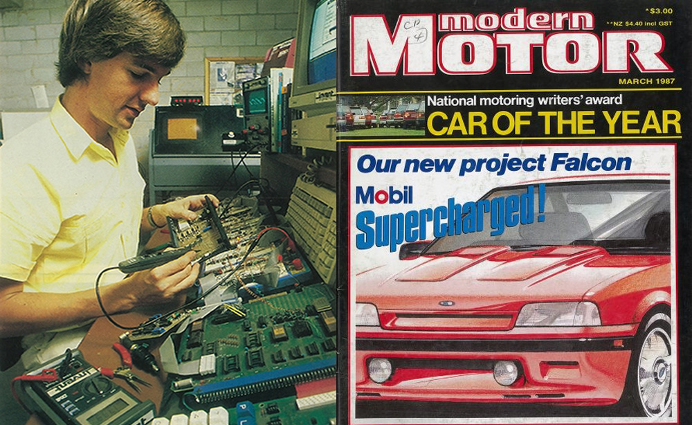
You may have seen in our Ten Things You Didn’t Know About Haltech video or learned elsewhere around the traps, that a project car from Modern Motor Magazine was instrumental in steering a young Steve Mitchell down the path of starting the Haltech we all know and love today.
Thanks to our good friends at ARE Media, the current owners of Motor Magazine (and therefore the back catalogue of its predecessor Modern Motor), in celebration of our 35th Anniversary, we’re able to take you for a peek into the pages of those old magazines that kicked it all off.
Between March and November 1987, Modern Motor editor, Barry Lake, chronicled the build of a bright red, Aussie-built, Ford XF Falcon dubbed the Mobil Modern Motor Falcon.
Due to Australian emissions laws at the time, Ford never offered the XF with a V8 engine, thus Editor Lake had hoped to fit an unleaded-fuel suitable V8 from a then-current model Bronco. However, in discussions with Ford’s Chief Engineer, David Ford, he learned that this was going to be too great an engineering task to take on – So the decision was made to fit the Falcon’s standard 4.1L six with a supercharger, which brought with it a list of challenges all of its own. Not in the least, adjusting the car’s electronics to suit the new engine requirements.
Barry assigned accomplished motoring journalist, racer, and all-round automotive “fix-it-man” Ed Vieusseux as the project manager and set some goals: The Falcon had to at least match the performance of some of the popular Aussie muscle of the day. Namely Peter Brock’s HDT Holdens. Plus it had to be street legal and comply with all Australian Design Rules, including exhaust emissions, so that it could be thought of as a true contender to the aforementioned Holdens.
What follows is the text verbatim from Part Four of the Project Car build, as published in the June 1987 Issue of Modern Motor, when “Fuelling the beast” was starting to become serious business. Republished with permission from ARE Media:
We had spoken to engineers all over the world about the problem of providing more fuel at the correct time and in the correct quantity for the requirements – very much changed from standard – of our Mobil-Modern MOTOR Supercharged Falcon. We had gone from the Ford Motor Company to specialist US automotive electronics companies which produce one-off computerised systems for prototype cars, to similar experts in the UK and also to anyone who was anyone in automotive electronics in Australia.
What we learned – or rather relearned – is that there are numerous ways of approaching any problem. We had suggestions that varied from relatively simple to highly technical; from adequate to highly efficient; and from relatively inexpensive to very costly.
A further factor in the equation was our desire to use local parts, technology and talent wherever possible and also that we wanted to do as much of the design and development work as possible ourselves. This was never intended to be a “kit car” built up from over-thecounter items readily available to anyone. This was to be our own design; a unique and well-engineered car.
We were pondering on which route to take with the electronic side of things when Ed Vieusseux, currently employed by us full-time on this project, stumbled across a genius operating out of a well-equipped and well-lit basement garage and workshop in a fashionable Sydney suburb.
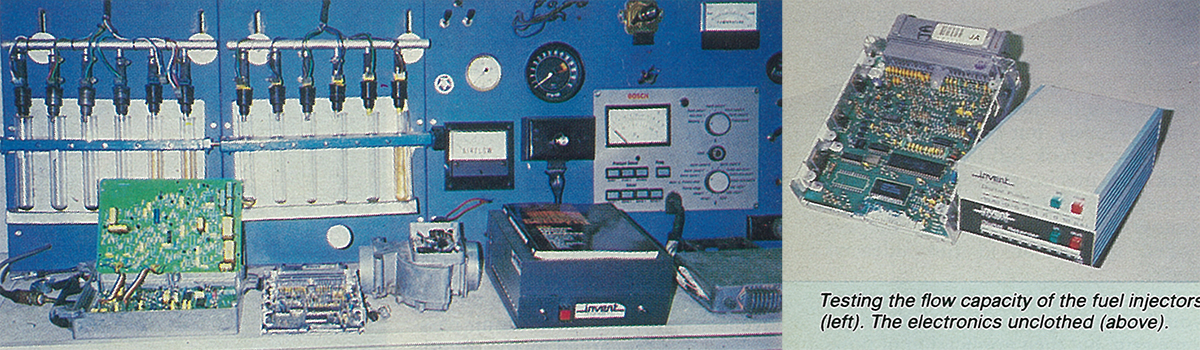
Steven Mitchell was a real find. He is a young man who has a list of achievements that belie his years. He studied electrical engineering at Sydney University and spent two years with Sadgrove and Bower Fuel Systems at Hornsby as grounding for his selfowned business Invent Engineering.
Steve’s speciality is electronic fuel injection and he supplies high-tech aftermarket electronic equipment to such companies as Benson’s Turbo Centre and The Turbo Connection, both in Sydney.
He is a car nut who has owned 26 assorted vehicles in the past five or six years, the latest brace being an Alfasud and a highly-modified and nicely dressed-up VW Beetle.
When Ed first heard of Steven he was told that he wouldn’t have time to look at our problem; he was too busy perfecting his most ambitious creation – a computerised diagnostic system that could analyse any electronic fuel injection system on any make or model of car, and which would more accurately pinpoint problems than current diagnostic systems.
Steve believes his unit will revolutionise the tune-up business, most operators being unable to afford an ever-increasing number of expensive and specialised diagnostic units for make after make of car
It turned out that Steve was extremely busy in his space-age hideaway – but not so much so that he was not interested in our project. He is the type of person who can not resist a challenge and doesn’t care how many hours a day he has to work to solve any new problem.
Steve saw the chance to help us as an opportunity to develop a fuel injection system that, suitably modified, could have a wide range of applications in the automotive after-market. It certainly wouldn’t do him any harm, either, to gain a name for himself in the business through the fame – if not fortune – that a successful relationship with this very special car could bring him.
Steve’s brief was to produce a system that would allow the car to perform well without flat spots or knocking, but it must still pass the government emission control regulations and remain fuel-efficient. In his own words: “This is a tall order.”
Please join us for the next installment where Barry takes us a bit deeper into the 1980’s nerdiness of early electronic fuel injection.