Category: Tech
How to read Power Curves
We all know that one keyboard warrior who brandishes their dyno sheet like a boy scout merit badge. But what does that big fancy number even mean in the real world? How does his/her car perform compared to others? And more importantly, does that three or four-digit number even matter? So, let’s dive deeper into power curves and how their results can tell us a story about a particular engine or car’s habits.
What is power?
To clear up some confusion, “power” and “work” are different terms. Power is the rate at which we perform work; Work is the action itself. Meaning, if we lift a 20-pound weight to a height of 10 feet in one second, we generated 200 foot-pounds per second of power.
Okay, but where does horsepower come from?
Well, James Watt (guy who helped design the steam engine) decided we need a common unit of measurement to determine power. Through testing, he established that a horse could lift 550 pounds at a rate of one foot per second. Thus, the term “Horsepower” was born.
That’s great! Now we have a unified standard for measuring power, but what if the work being performed is rotational (ie. Driven wheels, or spinning crankshaft)? We can calculate that by multiplying “torque” (rotational work) and speed (RPM), then dividing that value by 5252.
Wait, 5252?
Don’t worry, think of this as a constant figure used to convert units into something recognisable. Engine speed is measured as # of revolutions per minute (RPM), but Mr. Watt defined horsepower as 550 foot-pounds over one second. Add on the fact we are measuring speed and not distance, it becomes apparent that this conversion is needed. Here’s a quick breakdown:
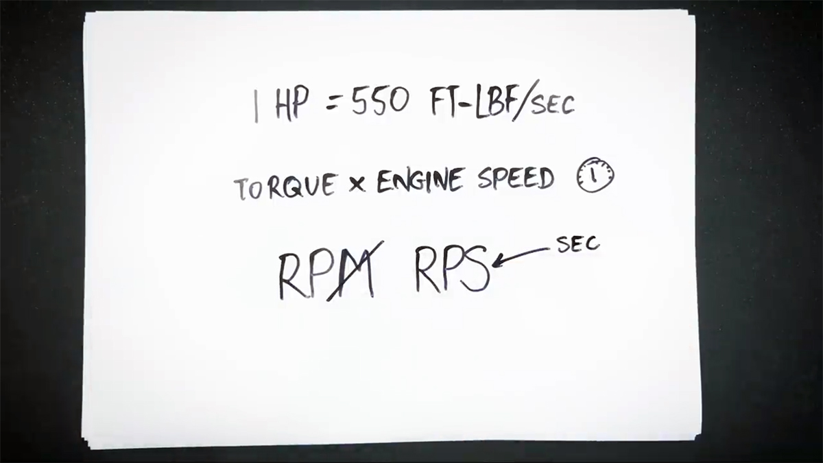
We know 1 horsepower is equivalent to 550 foot-pounds per second. Our dyno measures power in torque and engine speed, but we need to convert these values to our foot-pounds per second unit.
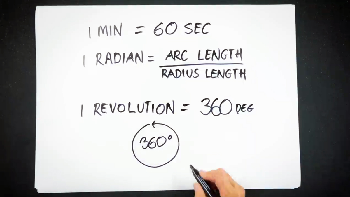
One minute is equivalent to 60 seconds, that’s understood. But, how do we account for length without a measured distance? With a radian. Think of it as a ratio of the radius of a circle versus a set length of the circumference (outside edge). Since we are measuring one revolution, that arc is equal to its radius (the same as multiplying by 1).
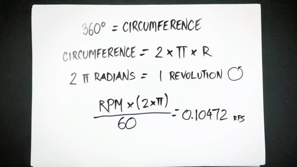
Wait, what? Yeah, that radian is equivalent to multiplying by 1 and this applies to all circles (because by definition they’re 360 degrees). So let’s convert that RPM to RPS (seconds) by multiplying it with the circumference (which has a radius/length of 1). Then convert minutes to seconds by dividing by 60. Voila, we now have 0.10472 RPS.
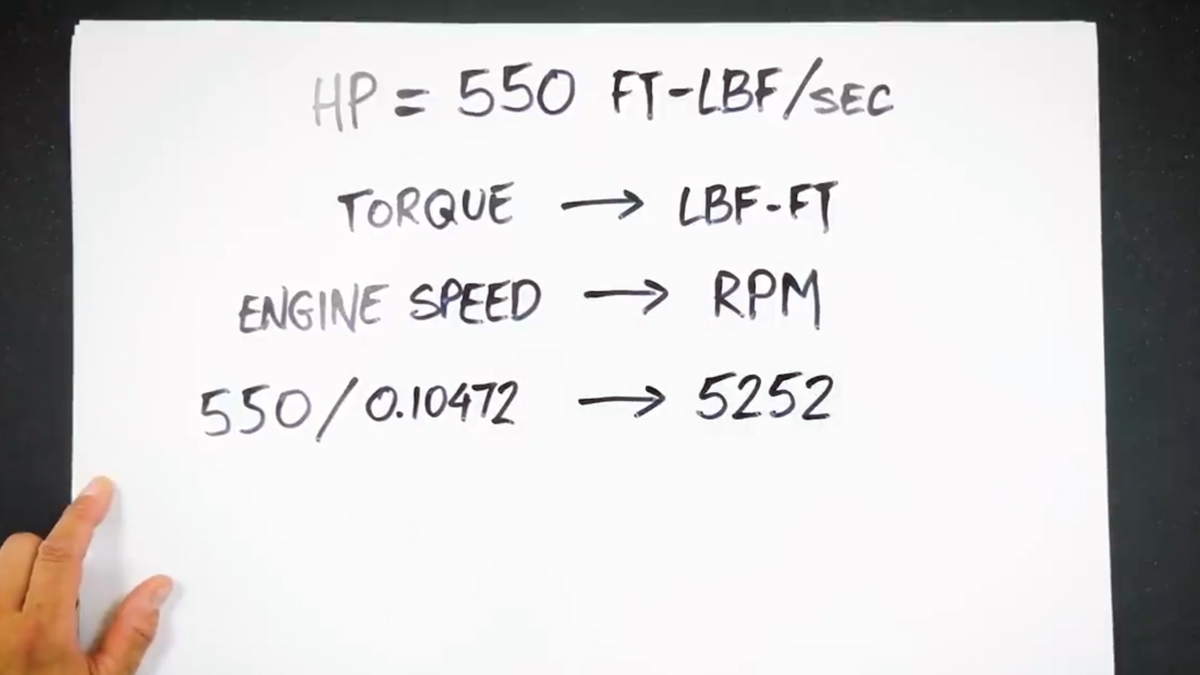
Now we have the ability to convert that 550 foot-pounds per second into a common value. Divide our 550 by the 0.10472 RPS to get…. 5252.
How do we measure it?
If you’re reading this, then you’re most likely an automotive enthusiast. Which means you have at least heard of a chassis dyno. But what are they and how do they convert screaming exhaust into a figure we can understand and tell our buddies about?
Dynamometers usually come in two flavours, the first and most simple are inertia dynos. These are essentially a very large, heavy steel drum that a vehicle is strapped too and calculate how fast you can accelerate that drum (quicker it is spun, the more horsepower you’ve made). They’re very useful for back-to-back power runs and for mechanical fuel tuning (carbureted engines).
The second and more useful type is known as a load-bearing (steady-state) dyno. They provide you with the ability to hold an engine at a steady RPM and measure the torque output in real-time. This gives tuners the opportunity to tune specific fuel cells for a more complete table.
For a more in-depth look at the various types including chassis, hub and engine dynos, be sure to check out Scott’s Dyno Tuning Basics video below:
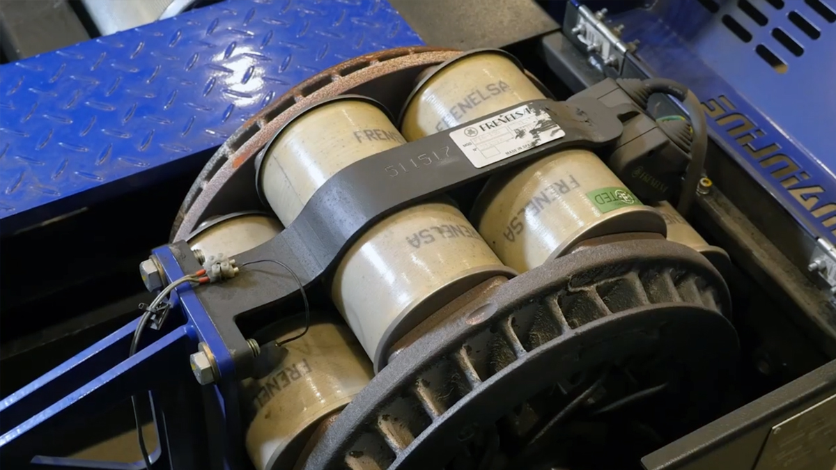
Looking at our own Mainline steady-state, we see the rollers themselves. The larger rollers spin freely and just help keep the tyre in place during a run.

The smaller, knurled rollers (rough, machined surface for traction) are attached directly to a retarder shaft. This shaft is slowed (retarded) by an Eddy current brake, which is a large electromagnetic brake that is powered to generate drag/load on the shaft.
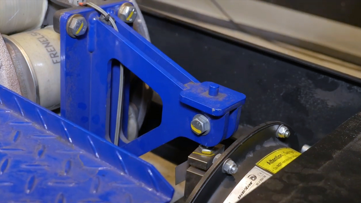
Do you see that blue bracket off of the eddy brake? That’s attached to the load cell, which calculates the amount of force that the roller is being subjected to.
There are variables such as heat, momentum, and mechanical loss taken into account when the final numbers are being generated. But in essence, with speed (RPM of the roller) and force (effort on the load cell) the computer can calculate the horsepower being generated against our chassis dyno.
What do we do with it?
Great, now we know what horsepower is and how it’s measured. But what are you supposed to take away from that fancy dyno sheet, what have you learned? Let’s have a look at a pull recorded on our dyno with a naturally aspirated four-cylinder engine.

This pull was done from a speed of 40 KPH – 150 kph, with the dyno only allowing a 20 KPH increase every second (for a total of 6 seconds). Notice the traced line in the top graph, this represents the horsepower output over the run. We see a total peak output of 165KW (~221HP) which is a respectable number for a non-power adder four-banger.
But, what’s more important is the shape of the overall curve. Think of this powering a daily driver, we wouldn’t see a huge delay in performance, it would be pretty responsive when accelerating from a low speed (imagine merging onto an interstate). No matter where we are in the graph, you could expect this engine to produce at least 45-50KW (~65HP) at the wheels. Which in a small vehicle would be plenty of power to move out of its own way.
Okay, great, but what would happen if we threw some boost at it?
Let’s have a look at a turbo R32 GTR. This is a modified inline 6 with a larger than OE turbocharger. Using the same pull/load (20KPH/sec), we see a very different curve shape. While the peak power output is 520KW (~710HP), triple what our four-cylinder engine made, you can see that the majority of that power did not show itself until around 140KPH.
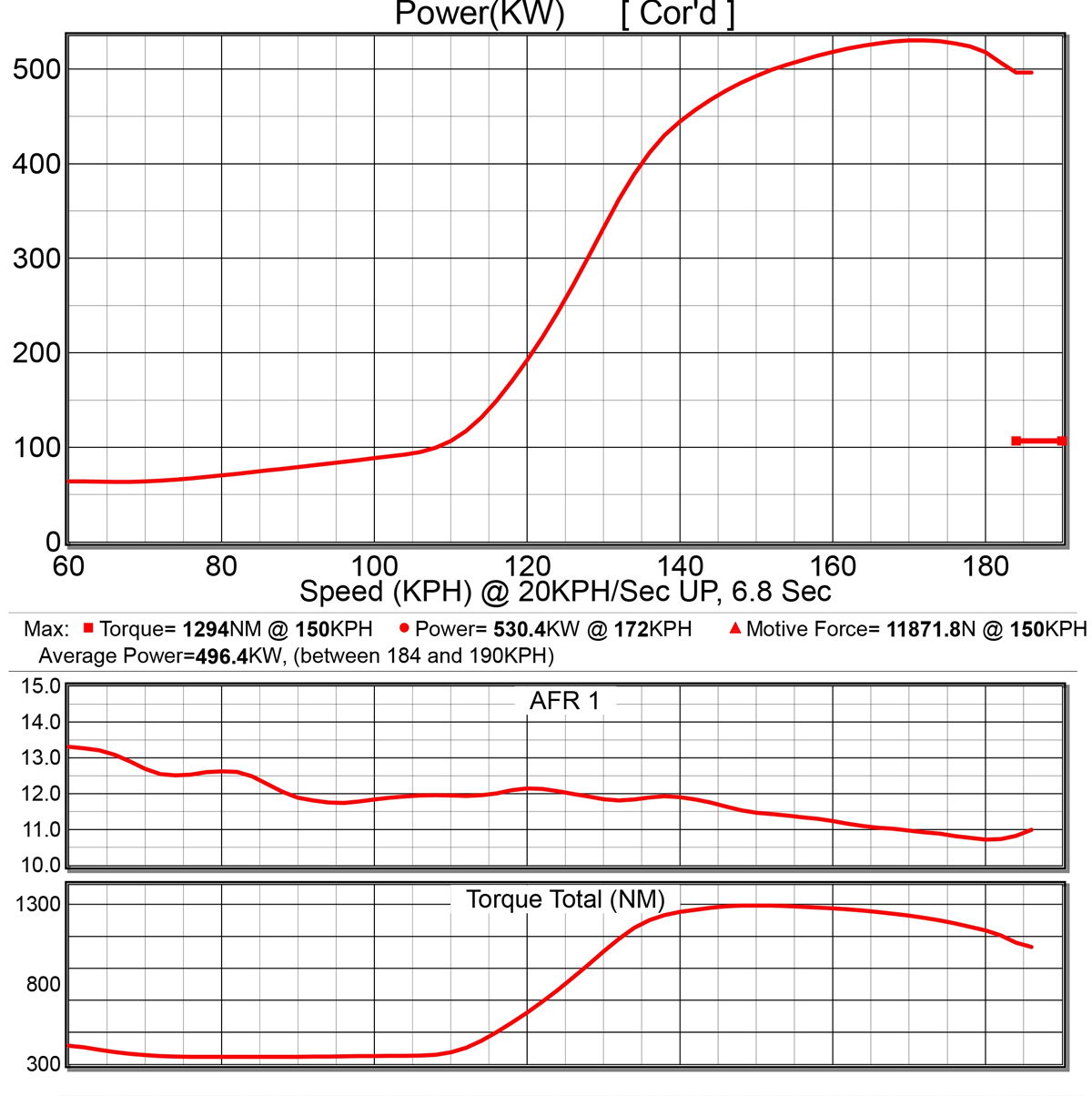
If this were a road-driven car, the smooth, yet lower power delivery of the four-cylinder would be much more enjoyable. But in a drag racing scenario, the sluggish inline-six would be an absolute riot at higher RPM/speed. This is why it’s important to choose an engine combination that suits your vehicle’s purpose.
Why is the “area under the curve” important?
Let’s look at the four-cylinder dyno graph again; we know that the line represents output over the entire run.

The area underneath that line is the total amount of effort (work) our engine produced. When we say we are looking to maximize the area under the curve, it means that we are looking to generate as much work/power throughout the entire rev-range. The larger the area under the curve, the more power we are making.
Why do we want it?
Okay, imagine we have a drag car with launch control, a modified differential and a racing-oriented transmission. This vehicle’s purpose is to generate maximum power to the track surface as fast as possible. Would it be worth the effort to generate large bottom end power, or could we focus on fine-tuning the engine to deliver horsepower at a specific higher-RPM band?

If we have the ability to utilise tools such as a 2-step and transbrake (both can be controlled with a Haltech ECU, by the way), then it’s possible to help isolate the engine’s power band. Think about the R32’s dyno sheet, that massive delay in power can be avoided/ignored with a few tricks. By keeping the engine in an area where it’s generating its highest Total Torque value, we know it will exert as much force as possible.
The Takeaway
Alright, what did we learn from all of this? That horsepower is a relative thing, and how fast your car is, depends on much more than just a dyno pull. Sure, there will always be keyword warriors who claim their big number as gospel. But looking at the overall shape of the curve gives a better understanding of where and how your engine will make power.
Base Map Basics
Default Map
When you go online with your Haltech ECU for the first time it will already have a preloaded Default Map. A Default Map has all the tuning maps, settings and functions initialised with general values which give the tuner a good idea of what each value should be as well as the rough shape that each map should have.
This Default Map alone helps to get things rolling as each default value is a general guide as to what’s expected for each input value. It would be much, much harder if all the values in the ECU were set to zero – not to mention a hell of a lot more typing!
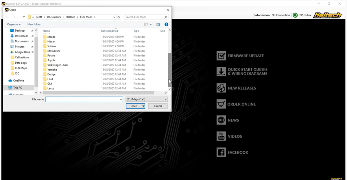
If you are working on a unique, one-off or experimental engine you’d be best off working from the Default Map, however if you have an engine that’s a little more common odds are we already have a Base Map to suit.
Base Map
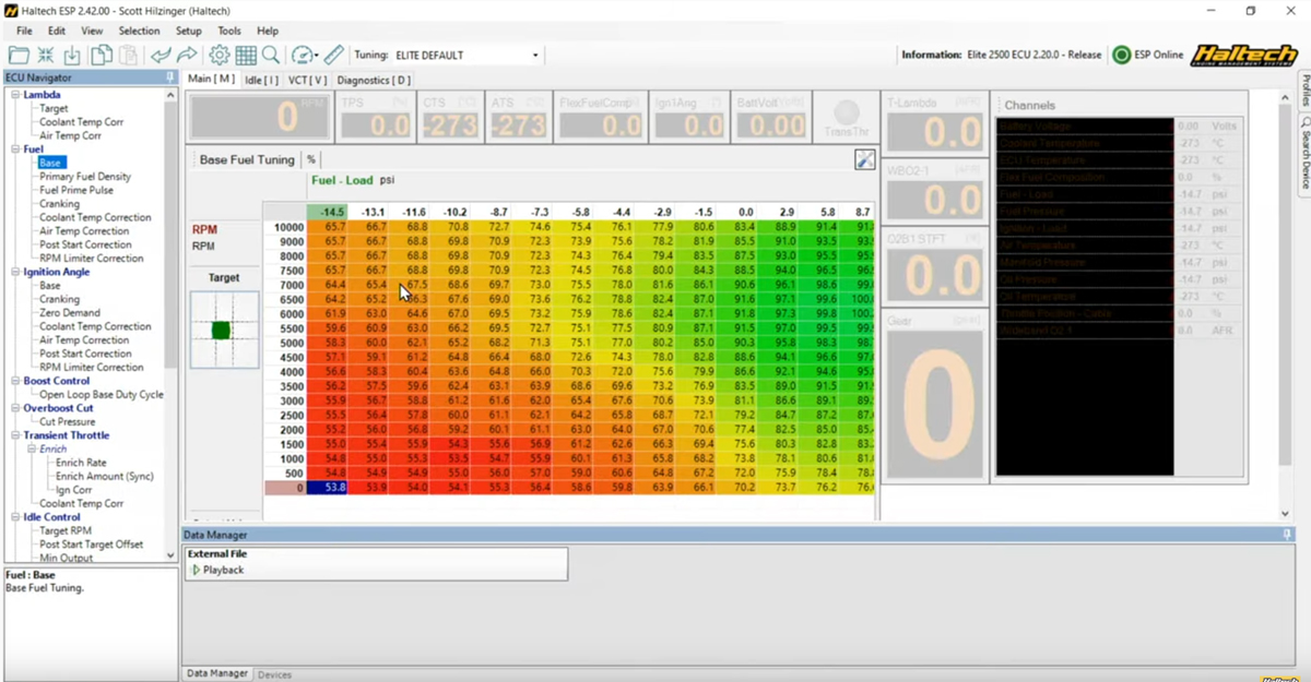
A Base map, as the name suggests is a base to start working from in order to get your engine up and running as quickly and easily as possible. A Base Map has as much information entered as possible, leaving only the settings unique to your setup left to add in. For example, let’s look at a GM LS2 Base Map.
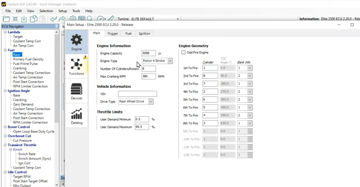
The Main Setup is filled in with the engine capacity, number of cylinders and firing order, while the Trigger system information is all filled in to suit the factory GM cam and crank position sensors. This is information that would be impossible for us to put into a default map because we never know what kind of engine the ECU is going on.
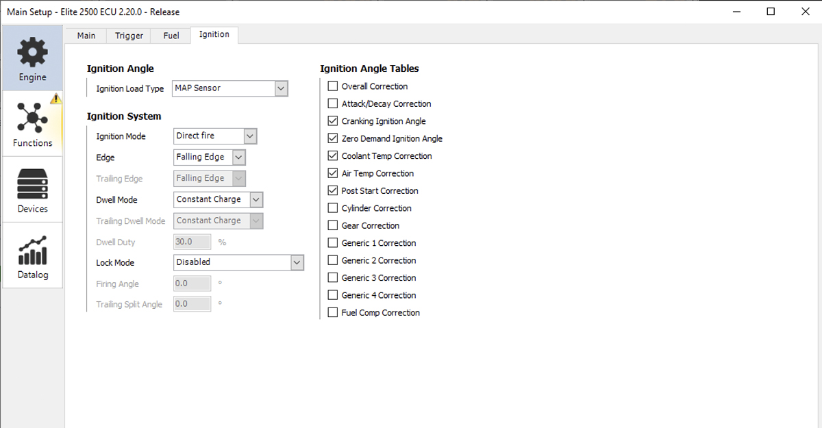
Let’s take a look at the Ignition and Injection settings – the number of coils and injectors will already be setup, but there are still things to check.
If you have a stock ignition system the Base Map settings will be fine, but if you have an upgraded ignition system make sure the coil settings and coil charge times are adjusted to suit the new system.
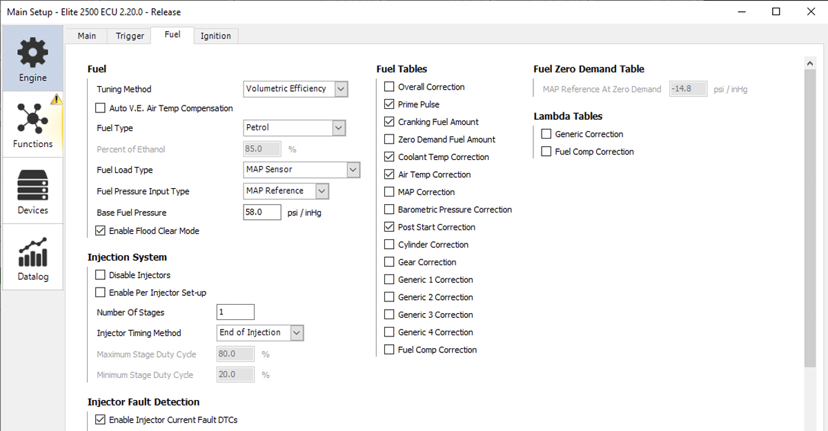
Likewise, Injectors are commonly upgraded to flow more fuel and as such we require the new injector characteristics to be entered before starting the engine.
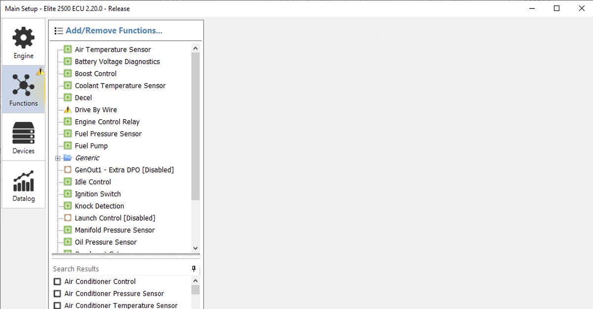
Next is the Functions page with all the inputs and outputs is setup but you need to check the inputs and outputs you’ve used in your car, against the inputs and outputs configured in the Base map.
If a base map is available for your car it’d be a good idea to open it and have a look at the Input Output assignments before you start wiring, that way you won’t have to adjust too much of the base map.
Remember to assign any extra sensors that you have added, Oil and Fuel Pressure sensors, Temperature sensors and Wideband Oxygen sensors are common ones that are not typically setup in a base map because we don’t know what inputs they would be wired to.
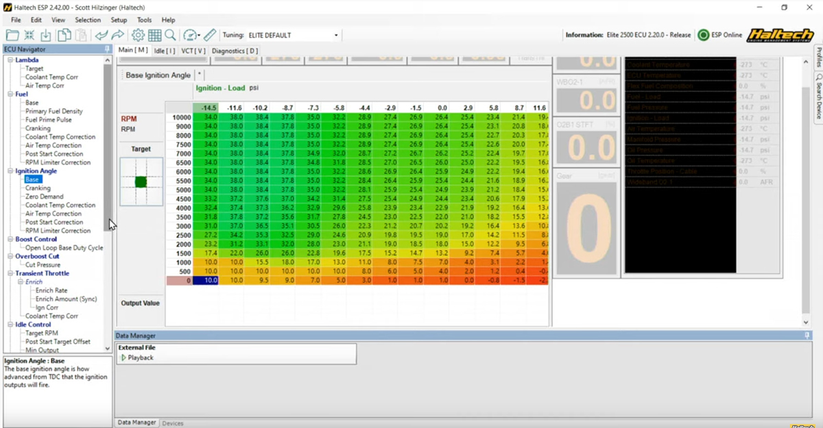
Once you’ve checked over the Main Setup and Input/Output functions you can then have a look through the Fuel and Ignition tuning tables. A base map will have table axes and values setup to suit your specific engine, but they’ll be tamed down and on the safe side.
What to expect from a Base Map
And so we come to the big question – what can you expect from loading a Base Map? You can expect a Base Map to get your engine up and running, to be able to check for fluid leaks, to bleed the cooling system and to move it around the workshop.
Now, Before putting the engine under any serious load it is best to get your tuner to take a look over everything and get the thing on the dyno. Tune it and make sure you’re getting the most power out of your pride and joy with as much reliability as possible !
The best way to familiarise yourself with base maps and learn how they work is to try them out.
Have fun!
How Intercoolers Work
We all know that engines like consuming cold air. In fact, the colder the intake charge the more power the engine will make, but why is that?
The basics
Air has a mass or a weight that changes based on the temperature and pressure of the air. The lower the temperature – the higher the mass. The higher the pressure – the higher the mass. At 15 degrees Celsius and at sea level 1 litre of air weighs around 1.225 grams. Of that around 0.245 grams is oxygen – the stuff we want to cram into the engine.
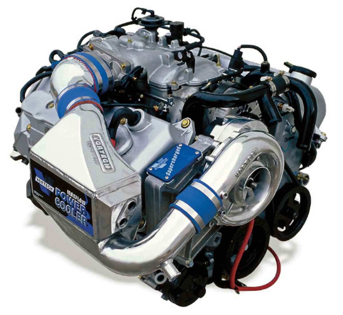
In order to get more air, thus more oxygen into the engine, we either need to compress the intake charge (turbo or supercharging), cool the intake charge, or both! This is where things get tricky because the process of compressing the air also heats it up, so we need to cool it before it makes its way into the engine – enter intercoolers!

What is an intercooler
An intercooler is a heat exchanger that’s fitted between the engine’s super or turbo charger and the intake manifold. Its job is to absorb and dissipate the heat in the charge air in order to provide the engine with the coolest and most dense air possible. There are two types of intercoolers, Air to Air and Water to Air.
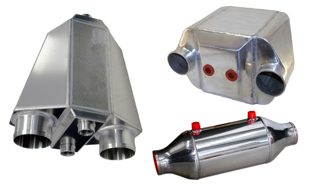

An Air to Air intercooler, as the name suggests, absorbs intake air temperature then relies on airflow over the intercooler to dissipate the heat.
A Water to Air intercooler is a little different. It still has an intercooler core, but instead of relying on air for cooling; the core is jacketed by water which is then remotely cooled in a conventional radiator system (normally independent of the engine coolant). These work really well when fitting a huge front mount intercooler is not convenient or possible. This method can also help in reducing the overall piping length of the intake system. The downside of a water to air intercooler system is that they are much more complicated and contain a lot more components than its air to air equivalent.
Checking your intercooler’s efficiency
There are two ways to measure this: Temperature Drop and Pressure Drop. It’s not uncommon to see charge air coming out of a turbocharger at temperatures of 100 degrees Celsius or more, then going through an intercooler which could drop the intake temps by more than half! As long as the intercooler is good quality and has good airflow it could do this indefinitely.
But there is a downside.The intercooler itself has to have some restriction in order to perform the heat exchange, this means if we put 15 pounds into the intercooler we might only get 13 pounds out.
Additionally, in dropping the air temperature we increase the air density which results in a pressure drop independent of the intercooler restriction! So next time someone tells you their intercooler has ZERO pressure drop but does a great job of cooling – ask for the data to back that claim up!
Having a pressure and temperature sensor before and after the intercooler is the best way determine whether your intercooler is working efficiently. Knowing this data you can make an informed decision as to whether an upgraded intercooler would benefit your setup.
Sensing The Speed – How Wheel Speed Sensors Work
A vehicle speed sensor’s job is relatively simple. It measures the speed of a rotating shaft and sends that information to the engine management system for processing.
The two most important things to know about wheel speed sensors are:
1. What kind of sensor to use
2. Where they can be located
The most common place to find a factory vehicle speed sensor is on the gearbox where you’d usually find a sensor detecting the speed of the output shaft which is directly related to road speed.
If there’s no sensor on the gearbox, odds are there will be a sensor looking at a number of teeth around a single wheel hub or even a sensor mounted on each of the four wheel hubs.

Having a sensor mount in every wheel hub usually means the car is fitted with ABS and these sensors are used to detect if a wheel’s locked up under braking. So our first task is to locate the sensor then determine what kind of sensor it is. It will be either Hall Effect (digital), Interrupt Style (digital), Magnetic Inductive (passive) or Magneto Resistive (active). It’s very important to know which type of sensor we are dealing with as the wiring techniques will vary depending on the sensor.
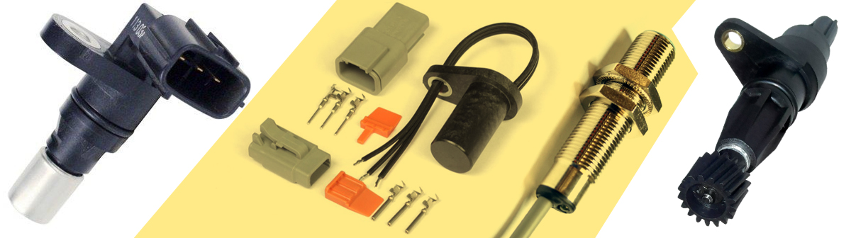
If you’re lucky enough to find a Hall Effect or Interrupt style sensor on the gearbox – things are pretty straight forward. All you need to do is share the factory signal with a Digital Input wire on your ECU and that’s it! If your car is fitted with ABS (that you’re still using) and it uses magnetic inductive or magneto resistive sensors then things can get a lot trickier, to the point where it might just be easier to fit a speed sensor of your own.
There is an art to sharing ABS sensors (especially magneto resistive style sensors) which requires extra electrical circuits to isolate the aftermarket ECU and ABS computer so one doesn’t upset the other. Sounds complicated? That’s because it actually is.
Fitting your own sensor on the other hand is not as daunting as it sounds. Grab a Hall effect sensor and make a mount so the sensor can detect something like the heads of the wheel studs (on the back of the wheel hub assembly), the bolts holding the front CV together or the bolts on a tail shaft. When fitting a new sensor have a think about which wheel you’re fitting it to. Is it the driven wheel (a wheel that will show wheels pin) or the undriven wheel (a wheel that will show road speed).
Typically it’s best to measure a driven wheel first, then add a second sensor to an undriven wheel. This way you can determine a slip percentage between wheels to build a traction control strategy if required.
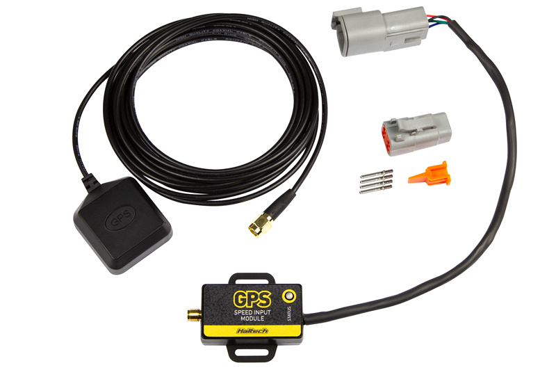
You can also fit a GPS speed module. This little gadget has a GPS antenna and a speed signal output and it’s connected to the ECU as if it was a non-driven wheel speed sensor. After you have your sensors fitted and wired to the ECU we just need to calibrate the number of pulses to the speed the vehicle is traveling.
This is a very simple process where we drive at a known speed (so, on the dyno or using a GPS speed app on your phone) then let the ECU know this speed and press “Calibrate” – that’s it! The ECU then determines how many pulses it receives at the known speed and can therefore determine road speed all the time. This takes gearbox ratios, diff ratios and rolling diameters into account so all the hard work is already done!
Once you have a road speed input, the ECU can send that speed information to a digital dash, set up speed limits like valet mode or pit lane mode, setup anti-stall idle control strategies so the engine comes back to idle nice and smoothly depending on road speed. You could also set up boost control strategies based on road speed and of course you could set up traction control strategies based on the difference between each of the wheel speed inputs.
So, while your ECU doesn’t NEED a wheel speed input to operate, it’s certainly a nice thing to have!
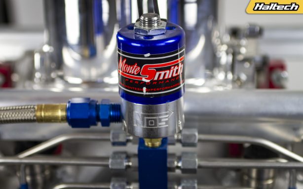
Nitrous – the forgotten power adder
Today we’re exploring Nitrous Oxide. What it is, how it works and most importantly – how to use it to make power!
How forced induction works
In order to make power our engines need air, the more air we can get into them, whether it be by increasing compression and efficiency or adding a supercharger or turbocharger the more power we can get out of them.

The air that we and our engines breathe is made up of about 21% Oxygen, 78% Nitrogen and a 1% mix of other gasses and it’s the Oxygen and Nitrogen in the air that we’re interested in.
Oxygen is the gas that we ignite and Nitrogen’s the gas that expands when it gets hot and pushes the pistons down.
The more Oxygen and Nitrogen we can fill the engine with – the more liquid fuel we can add and the more power we’ll make. So why don’t we just inject pure oxygen?
Firstly, pure oxygen is pretty dangerous and while it is not flammable itself it does act as an oxidiser and can make things a whole lot worse if a fire is present. Secondly, if you inject pure oxygen you’re displacing the nitrogen that we need to expand under the heat of combustion to make power – this results in ridiculously hot combustion temperatures but with a lot less expansion and that means less torque and less power.

The best way to make more power is to make the intake charge as dense with Nitrogen and Oxygen as possible. Enter Nitrous Oxide!
What is Nitrous Oxide?
Nitrous Oxide, commonly referred to as Nitrous or NOS (one of the popular company names) is a chemical compound made up of two parts Nitrogen and one part Oxygen with the chemical formula N2O.

It is stored as a liquid above around 735psi and its used in our racing applications at around 950psi. Temperature plays a huge role in the bottle pressure and is something that we need to be monitoring and controlling in order to use it consistently and safely.
The pressure of the bottle will increase by nearly 100psi per 5 degrees Celsius until we get up to around 27 degrees Celsius, then small changes the bottle temperature can increase the bottle significantly.
For example if the bottle changes from 27 to 30 degrees Celsius you can expect to see a rise in pressure from 850 to 950psi!
It’s important to know this because a change in pressure makes a big change in flow and a big change in Nitrous flow means a change in the engine’s fueling and ignition requirements for its newfound charge!
How does it work?
While Nitrous Oxide is making its way into the engine two magical things happen. First – it comes out of the fogger from very high pressure to very low pressure and because of thermal expansion it becomes very cold, very quickly. This reduces the engine’s natural intake charge making it more dense simply by cooling it. The second thing that happens is that it heats up!

When it gets hotter than about 300 degrees Celsius Nitrous Oxide splits into two Nitrogen atoms and one Oxygen atom. The Oxygen atom aids in the combustion event that’s occurring with the engine’s fuel while the Nitrogen hangs out with the other Nitrogen atoms in the cylinder and expands when it gets hot.
This is why you may have heard Nitrous Oxide being referred to as a “Chemical Supercharger”, because the end result of using it is a more dense cylinder charge, much like a boosted engine.

Different Types of Nitrous setups
Single Nozzle: This is the most basic Nitrous setup. A nozzle is inserted into the intake manifold or throttle body and the nitrous or nitrous/fuel mix is introduced to the engine via that single point. Simple to install and set up, the Single Nozzle systems are also the least precise.
Plate: This system uses a spacer placed between the throttle body and intake ports with holes through which nitrous or nitrous/fuel mix is introduced into the intake stream. These systems are usually application-specific and thus easy to install. They provide more precise distribution than Single Nozzle systems.
Bar: Similar to the Plate system, a Bar setup utilizes a hollow tube with a number of holes drilled along its length, placed inside the intake plenum.
Direct Port: This is the most advanced and most precise Nitrous injection type. Nozzle/s are inserted directly into each intake runner as close to the port as possible. This system allows for a more controlled and even distribution of Nitrous and permits multiple stages of injection to be used at each port.
Dry vs Wet
The addition of Nitrous Oxide into the intake stream requires additional fuel. That fuel can be delivered as via the existing fuel injectors or via a separate, solenoid-controlled fuel lines.
A “Wet” Nitrous system consists of Nitrous and Fuel lines operating in tandem and introducting both Nitrous and extra Fuel to the existing mix.
A “Dry” system uses an existing fuel system (controlled by an ECU) and only adds Nitrous Oxide to the mix while the ECU makes the necessary changes to achieve the optimal air/fuel ratio.

Wet nitrous kits are susceptible to backfires mainly due to the fact that fuel vapors can work their way into the intake tract where they could ignite. This is why a Dry and ECU-controlled Nitrous injection is a safer option.
The Purge
You will often see Nitrous injected drag cars purging their Nitrous at the start line before staging. What they are actually doing is pushing the air out of Nitrous feed lines. When they can see a stream of Nitrous Oxide coming out of the purge nozzle it means the feed lines are now full of Nitrous Oxide which will then be sprayed through the fogger when the system is activated.

If the Nitrous feed lines still have some atmospheric mixture in them, when the Nitrous system is activated the first batch of gas sprayed through the fogger will be the left-over atmospheric mix rather than pure Nitroous Oxide.
Benefits of the ECU-controlled Nitrous Injection
Nitrous will only be activated when the engine can accept it – ie within the right RPM range, over the right throttle amount (70% or more), within the right coolant temperature.
Setting the parameters for Nitrous activation prevents a potentially dangerous Nitrous accumulation in the intake.
ESP software provides infinite tuning options allowing you to adjust fuel, timing and retarding ignition, all of which can in turn yield more performance gains.
You can also map other engine operating conditons like adjusting variable cam control and VTEC activation points in order to maximise power in conjunction with Nitrous Injection.

In a typical single stage Nitrous injection setup (above), the ECU controls the Nitrous solenoid and also monitors a number of other engine parameters in order to calculate a safe “window” in which to activate the Nitrous injection.
A quick guide to Nitrous kit sizing
Nitrous aficionados often refer to “shots” to measure additional power gained from the Nitrous injection. A “100 shot” means you can expect an extra 100hp when the system is enabled.

The rate of Nitrous flow is determined by the size of the jet. A jet is the small insert with an even smaller orifice that sits inside a fogger and restricts the flow of Nitrous into the intake airstream. It is sealed by the jet face which is machined at a 37° angle to mate with AN style fittings.

Nitrous jets come in different sizes from a modest .003 thou to .067 thou or even bigger! Below is a simple conversion guide based on a single jet system.
.033 = 50hp at the engine, 40hp wheels
.041 = 75hp at the engine, 65hp at the wheels
.047 = 100hp at the engine, 84hp at the wheels
.067 = 200hp at the engine, 167hp at the wheels
By adding multiple jets you can quickly arrive at substantial power increase:
0.033 x 8 = 420hp at the engine, 355hp wheels
Now for the bad news…
Unfortunately there are also some downsides to using Nitrous. The tank doesn’t last forever and it can become expensive to use on regular basis.
A 10 pound or 4.5 kilo bottle will cost you around $150 dollars (in Australia) to have filled and you can expect it to make around 100hp for around 100 seconds. That means you will be using 0.1 pounds or . 45 grams of Nitrous per second. Of course bigger kits will use more and smaller kits will use less but you get the general idea.
It’s for that reason that Nitrous injection is more common on a drag style car and less common on a circuit car where physically storing 10 or 20 pounds of Nitrous as well as performing re-fills during a race would be a challenge.

Controlling Nitrous Injection with a Haltech ECU
All Haltech Elite ECUs from Elite 750 up offer Nitrous control functions. The amount of Nitrous stages vary from one on Elite 750, 950, 1000 and 2000 to six stages on Elite 1500 and 2500. The VMS and VMS-T also control up to six Nitrous stages.
Elite 550 – None
Elite 750 and 950 – Single Stage
Elite 1000 and 2000 – Single Stage
Elite 1500 and 2500 – Up to 6 Stages
VMS and VMS-T – Up to 6 Stages
The video below will guide you step-by-step through the various stages of Nitrous control setup on a Haltech ECU.
ECU Grounding – the DOs and DONTs
If you follow any online forum where vehicle wiring is discussed it won’t take long before you come across a debate about the best way to ground your ECU. So today we are going to get our nerd on and look at the theory of electronic circuits and help you figure out the optimal grounding solution for your particular wiring application. First let’s look at some of the problems we’re trying to avoid, analyse them and figure out how to optimise the ground layout for each of the cases.
Circuit = Closed Loop
The fundamental rule that applies to any electrical circuit is just that – it is a circuit. And by “circuit” we mean it’s a complete loop. We have one side of the battery that has a power supply, there is a device that we are controlling or a sensor we are reading a value from and a ground. The ground completes the circuit loop back to the battery.
In the case of an automotive electrical system the whole vehicle is made of metal and therefore conducts electricity so rather than running 2 wires to every device, we put a wire between the battery negative and the vehicle chassis. Now the whole vehicle is effectively the return loop that allows current to flow back to the battery.
So Chassis = Ground right?
This is where things can start to get confusing for some people, because in our ECU wiring harness we also have “Ground” wires. We have battery ground wires and also separate signal ground wires.
It’s all too easy to look at these wires and say: “OK, ground is ground, its just a loop back to the battery” but it’s not that simple. While it’s very tempting and quite possible and to connect all these black wires to the chassis just about anywhere it’s definitely not advisable.
Da Voltage Drop
Remember that every wire in the system can carry current and every wire has a different resistance. This means you’re going to get a voltage drop across each wire and that voltage drop will vary depending on:
• the length of the wire
• the wire gauge
• the amount of resistance in the wire
• the number of joins in the wire
• the amount of current flowing through the wire
Since we’re talking about this in the context of ECU grounding, let’s look at voltage from the ECU’s perspective and then predict what can go wrong due to different voltage drops.
Bad Example No.1
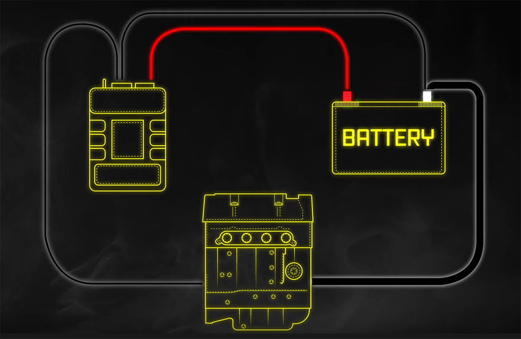
In this first example, we have grounded the ECU to the engine and also to the battery.
One of the reasons this happens a lot is because when you see ground straps on both the battery and between the block and the chassis you could be forgiven for thinking: “if one ground is good then two is better!” That, however, is not the case. Let’s take a look a the problems this can cause:
During cranking, a lot of current flows through the ground strap between the engine and the battery, so there’s a voltage drop between the engine and the battery. When you have multiple ground wires that connect between the same 2 points, the current is shared between the two alternate ground paths. In other words, the ECU shares some of the starter motor current.
Exactly how much of that current is shared depends on the relative resistances between the ECU ground and the ground strap. If the ground strap is in good condition then not a lot of the current is shared, but when this ground strap is not in good condition or you forgot to tighten that bolt or painted the block underneath reducing the contact efficiency then all that starter motor current now gets carried by these other wires. Wires, which were never designed to run a starter motor!
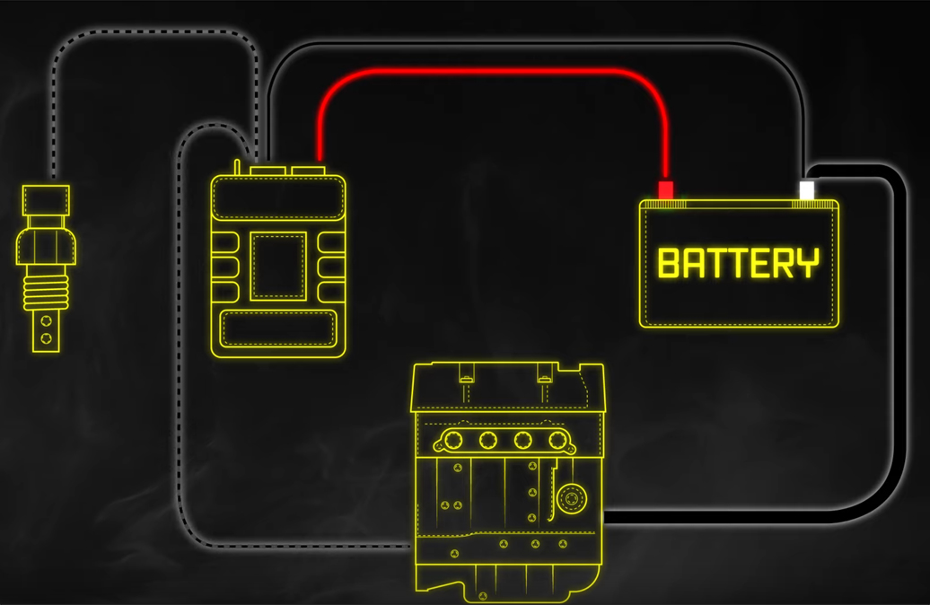
Bad Example No.2
Another similar but different example we often see is where the sensor ground is externally grounded. Because the ECU is already grounded through the power ground wire we are creating parallel ground paths again and a similar thing occurs to the previous situation with the starter motor – but in a less extreme way.
When injector duty cycle increases, the average ground current of the ECU will also increase, and therefore so will the voltage drop between the ECU and the battery. Creating an alternate ground path for the sensors will have a different voltage drop and offset the output reading of any sensor that connected to this alternate ground path. The result is erratic sensor readings which can play havoc with the way your ECU adjusts your engine tune.
Bad Example No.3
In this last example, the car has coil-on-plug ignition, the coils are grounded to the engine and the ECU is grounded to the battery. As the engine speed increases, the alternator charge current increases and the voltage drop between the engine and the battery increases.
Let’s assume the grounding to the ECU from the battery is also substandard, which means that as injector duty cycle increases, the voltage drop between the ECU and the battery also increases. We now have a double effect causing the ECU ground to sit higher than the engine ground. The coils however are grounded to the engine which means when the ECU is outputting zero Volts on its ignition output, the coil sees a positive voltage (equal to the voltage drop described earlier) on its input.
Some coils with built-in ignitors only need 0.7V to trigger, which means that in extreme cases you could even get the coils to trigger by themselves and that’s really bad! No engine likes random ignition coil firing! In all the examples above the problem is common impedance paths. The solution for this is star point grounding.

Start Point Grounding
How does it work? You pick a single point for your ground and reference all grounds to there. It doesn’t really matter whether this point is the engine or the chassis or the battery negative, but there are other factors which you need to be aware of. For your sensors you should only use a signal ground that is supplied from the ECU. That’s why this wire exists so don’t be lazy and just run a wire from the sensor looped around to the engine.
There are circumstances where a sensor’s ground is not isolated from the body of the sensor and it has to screw onto the engine. For example some cam angle sensors, narrowband oxygen sensors and many knock sensors ground through the body of the sensor. In this case you have a choice – you could replace the sensor with one that has a separate ground wire (away from the sensor body) or you could choose the star point grounding location to be at the engine.

What’s the best location for star point grounding?
We usually recommend the cylinder head because it minimises the likelyhood of a voltage drop causing random ignition events. It also allows for those sensors that ground through the body of the sensor to be used in their native form.
If you have any questions shoot us an email on [email protected]
Hall Effect or Reluctor?
The two most important sensors on your engine are the crank and cam sensors, so it’s super important to ensure they’re installed, wired and configured correctly.
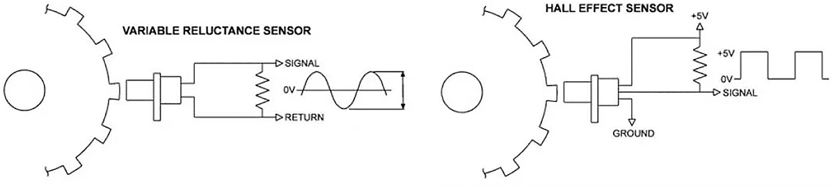
Sensor Type: Hall Effect
A Hall effect sensor typically has 3 wires. Power, Signal Ground and the Signal Output. It produces a consistent digital square wave signal each time a magnet or ferrous metal passes the tip of the sensor, regardless of the speed at which the trigger material. This makes configuring the ECU to trigger off a Hall effect sensor very simple as you expect the same signal each time a tooth passes the sensor.
When choosing a Hall effect sensor make sure it is compatible with:
• the trigger tooth target material
• tooth width
• tooth gap
• tooth height
Your sensor should also be capable of handling the tooth frequency (the number of teeth it can count in a certain amount of time). We usually recommend fitting a sensor without any inbuilt filtering as these may cause havoc when you’re trying to detect a missing tooth on a crank trigger wheel.
Hall effect sensors typically like an air-gap (the distance between the sensor and the target material) of around 1mm or 40 thou. Check the sensor’s spec sheet to confirm. Hall effect sensors also tend to dislike high temperatures, so again check the spec sheet. Generally, you shouldn’t expect Hall effect sensors to work much above 90 degrees Celsius unless otherwise stated.

Sensor type: Reluctor
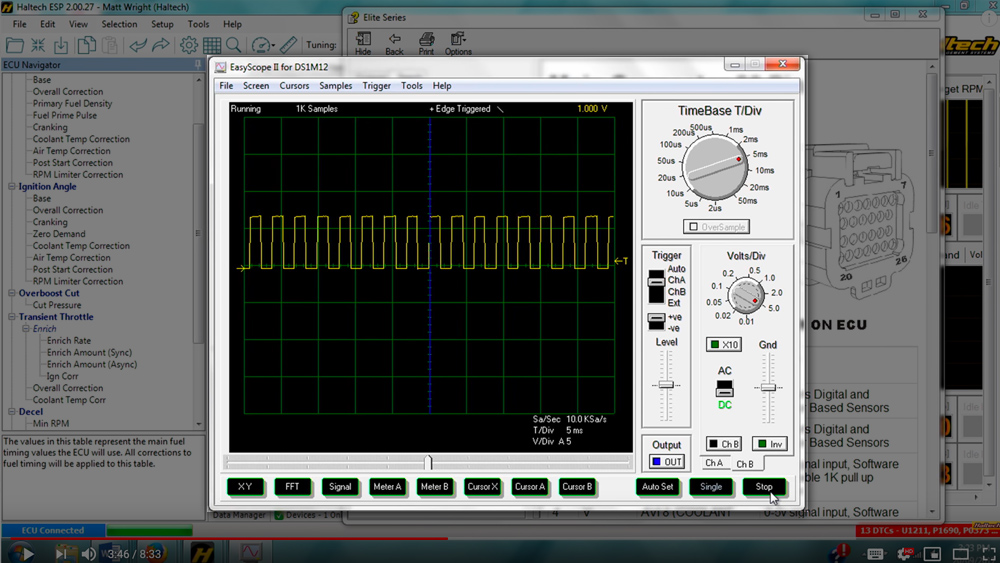
A Reluctor sensor is typically a 2 wire sensor and does not have any fancy electronics. A Reluctor is made up of a permanent magnet, a ferromagnetic pole piece, and a coil of wire. Each end of the coil of wire is refered to as the Reluctor +ve and Reluctor -ve which are the signals that are fed into the ECU.

Because of the lack of electronics inside the Reluctor sensors can typically handle temperatures much higher than the Hall effect sensor. It’s not unusual to see them working in environments over 200 degrees Celsius. The Reluctor sensors are much more sensitive to the Air Gap between the sensor and the trigger material. Getting that gap right is critical, it must be exactly the same between teeth and it is a much tighter gap than in Hall effect sensors, down around 10 thou or 0.25mm or even less in some cases.
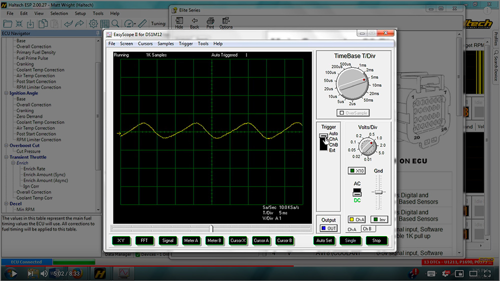
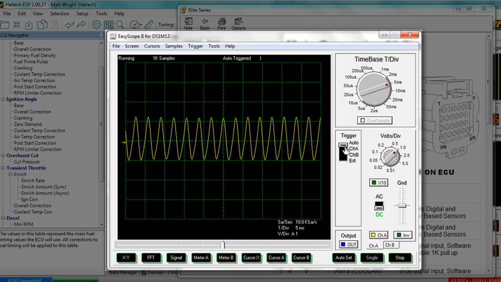
This places additional demands on the trigger sensor mount as the margin for error is much less than with a Hall sensor. Instead of producing an easy to interpret digital square wave like a Hall effect sensor, the Reluctor sensors output magnitude is proportional to the trigger target speed. Basically, the faster the trigger tooth comes past, the higher the signal voltage the Reluctor sensor will generate.
This presents a problem in that the noise the sensor generates also becomes higher, and the exact triggering edge that the ECU calculates the ignition timing off is also more complicated to interpret.
Trigger Input Wiring
For a Hall effect sensor use:
5V, 8V or 12V supply to the sensor (depending on its requirements)
0V Signal Ground and Trigger + which is connected to the signal wire from the sensor.
For a Reluctor sensor use:
Trigger+ to the positive side of the reluctor sensor
Trigger – to the negative side of the reluctor sensor.
Pay special attention to this wiring, as mixing and matching sensor wiring will cause all sorts of nightmares.
Conclusion
Hall effect sensors are easy to mount and easy to configure in the ECU software, however they don’t like getting hot and depending on the model may “filter” or miss teeth that you really want to detect.
Reluctor sensors don’t mind the heat and are extremely reliable, however they require time in setting up the trigger voltages vs. engine RPM and require a very accurate sensor mount in order to provide a very small gap between the sensor and trigger tooth to ensure trouble free operation.
Want to know more?
Check out these videos for more information of various engine sensors and how they work.
How Launch Control Works
Today we’re delving into the subject of Launch Control. What it is, how it works and how it can help you win races! But before we get into the specifics of things, we need to understand the problem that we’re trying to solve.
The Basics
In order for a car to launch consistently we need the engine RPM, throttle position and manifold pressure to be in a state that makes exactly the right amount of power in order for the car to take off as quickly as possible every time.
We also need to be able to alter this launch power depending on the racing surface and the track conditions. In order to achieve these right launch conditions we employ a function universally known as Launch Control. This fairly ambiguous term describes a whole range of different engine management functions.
Is the car automatic or manual? Is it turbocharged or supercharged? Does it make the required launch power under its own steam or does it need a little help to get there? Let’s go through a few common scenarios and explain what’s actually happening in order to get the car to take off.

Aux RPM Limiter
The most basic form of launch control is the Auxiliary Rev Limiter. When the clutch or brake pedal is depressed or the trans brake is active a secondary engine rev limiter is activated preventing the engine from revving past this value.
Let’s use 5000RPM as an example. The engine will react exactly the same as it normally would (same fuelling, same ignition timing), except the rev limiter that’s normally at 9000RPM is now at 5000RPM.
We have the option of cutting fuel, ignition or both in order to achieve a consistent launch RPM, as well as the option of a hard cut, soft cut or cut-off rev limiter. All these allow us to change the sound and speed of the rev limit noise from smooth and relatively quiet to aggressive and wild!
This limit allows the driver to hold the throttle flat and the engine to bounce off the lower rev limit in order to launch consistently.

Launch Control
Building on this strategy, we can now look at the Launch Control function, which is similar to the Aux RPM Limiter but with a little more functionality. This feature controls the launch rev limit but allows us to map the limit vs. a 3D table. We can look at throttle position and boost pressure for example but you can choose any tables.
This allows the driver to have a higher launch RPM at 50% throttle and low boost, thus inducing more exhaust flow, resulting in more boost pressure, resulting in more power.

When the desired boost pressure has been achieved the driver can go to full throttle which will drop the engine RPM to the mapped launch RPM and you’re ready to go!
The same method of mapping the launch RPM vs. throttle position can also help tame big, powerful, fire breathing drag cars when trying to bring them into the staging beams, reduce engine wear as much as possible and even confuse your competitor when the RPM limit keeps changing depending on the racers right foot.

The launch control function also allows us to make fueling and ignition changes while the function is active. Typically a little more fuel would be added in order to assist with in-cylinder temperatures, but the ignition timing is a little more tricky.
If the engine’s turbocharged and equipped with a Clutch then you’d want to massively retard the ignition timing so the spark event occurs after top dead centre – sometimes up to -20 degrees or even more.
Firing the ignition event this late means the exhaust valve will be open or just about to open and all that energy goes straight into the turbochargers exhaust housing and spools the turbocharger up. Once the engine’s making boost pressure (loaded against the retarded ignition timing) it is then making power.
With this power it can make more power and finally get to the desired launch RPM and boost pressure but without loading the engine against the retarded ignition timing it wouldn’t ever get there.
This methods is sometimes referred to as Launch Anti-Lag, however with this method there’s no exhaust manifold air injection like you have with Rally Anti-lag.

Using the Torque Converter
If the engine’s bolted to a torque converter then we need to tackle this a little bit differently. The engine already has something to load against so retarding the ignition timing will only hurt the engine power and even stop the engine from coming on boost.
The best method in this setup is to apply the trans or foot brake then apply full throttle. If the engine reaches the desired launch RPM and manifold pressure then things are good, if it doesn’t – we might want to add ignition timing to try and increase engine power in this area.
Keep in mind however the ignition map should already be tuned in this area to make the most engine power possible.

Using Nitrous
If you still have no luck, you might want to increase the engine’s down low power using Nitrous and the Elite’s advanced nitrous control strategy. We could add a dry Nitrous fogger which would be activated only when the trans brake input is active and when the engine is below the launch RPM.
All the same safety features are used, like the engine needs to be over a pre-programed coolant temperature, between chosen manifold pressures and over a certain throttle position. The ECU then triggers the Nitrous solenoid and applies the desired ignition retard depending on how much Nitrous is being used.
If it still doesn’t come up you could either add more Nitrous or change to a more slippery torque converter – but that’s going to be a lot of work!
You could tie any of the Launch RPM methods together to create a kind of “3 Step” style strategy where the first step is a Burnout Limit, the second is the Launch Limit, and then finally the third “step” is the engines main RPM limiter.
As you can see, there are many options available and it’s not really just three “steps”. Each limit has its own flexibility resulting in different limits for different situations which results in different outcomes. And each can be programmed to get the perfect launch from your car every time.

They see me cruisin’ – How to set up Cruise Control on your Elite ECU
Events like Drag Week in the USA and Drag Challenge here in Australia are becoming increasingly popular. Because these epic challenges involve taking street registered vehicles and driving them over vast distances for multiple days hopping from one race track to the next, features like cruise control in your aftermarket ECU are becoming more and more of a must have!
So, in this article, we look at how to setup and calibrate cruise control on a Haltech Elite 1500, 2500 or Elite Pro Plug-In series ECU.
The first thing you need to know is that for the cruise control function and work safely there are quite a few conditions that need to be met:
- Your engine must be using an electronic drive by wire throttle (Available only on Elite 1500, Elite 2500 or Elite Pro Plug in (Barra) ECUs
- You must have a vehicle speed sensor of some sort coming into the ECU (either a drivetrain sensor from the transmission directly or a wheelspeed sensor).
- You must have a brake pedal switch coming into the ECU.
- Your vehicle must have either gear detection setup, or a neutral switch wired in
- If you have a manual transmission, you must also have a clutch switch wired into the ECU
- If you have an Automatic transmission you must have a gear selector position input enabled
As you can see, there are quite a few ‘must haves’ that need to be met before cruise control can be setup. Don’t worry if you can’t remember all of these things though – one handy feature of our ESP software is that it will not allow you to setup a function to completion if all the conditions for that function haven’t been met.
For example, if you attempt to setup cruise control but forget to setup a brake pedal switch input, you will get a red error message explaining why the function cannot be enabled.

With all the background setup done, lets get on to actually setting up the cruise control functionality.
Navigate your way to the main setup page and search for cruise control. The first thing you notice is that there are three possible connections that can be made. The input selection, that is how is the ECU going to be told when to turn the cruise control on, turn off, accelerate, slow down etc. and two outputs, these are used to indicate that cruise control as a function is enabled and the other output is to indicate cruise control is actively controlling the vehicle speed.

Lets take a look at the input connection first, we have two options: CAN input or analog. We’ll tackle the CAN input first. If, for example, you have one of our Ford Falcon Elite plugin ECUs, the cruise control request information is transmitted to the ECU not through a simple voltage input, but rather by discrete messages on the vehicles onboard communication system, known as the CAN bus.
This data stream is specific to each vehicle, so if you plan on using the vehicle’s CAN input for cruise control requests, then you will need to first setup one of the ECU CAN bus systems to read that specific vehicles CAN bus. To do this click on the devices tab, in the vehicle bus dropdown select your vehicles CAN bus system and if its supported – you are good to go.

For the rest of us where there is either no factory CAN bus because we have say a 64 nova drag week car, or its simply that Haltech does not yet support your vehicles OEM CAN bus, then we need to graft in a control system that consists of a series of buttons that tells the ECU when to turn cruise control on and off.
By far the simplest way of doing this is to retrofit an OEM cruise control input to either a steering wheel or an indicator stalk, like this one.
The way these systems work is that each button on the stalk or steering wheel sends a different voltage level to the ECU then within the ECU we program each voltage level with a cruise control function such as turn on, speed up, coast down etc.
Wiring up the cruise control input switch is typically just two wires: A signal ground and an input signal wire that goes into the assigned AVI input pin on the ECU.

Because there is no defined standard or how many features a cruise control system should have you will need to match the level of functionality that your cruise control system has with Haltech’s cruise control function – to make sense of this lets go to the ESP software and look at the buttons tab, here you will see that you can have a cruise control system with up to 6 buttons.
To calibrate which button does what and the voltage provided for each function, simply select the desired functionality of the button press from the dropdown menu.. Because all systems have a “rest position” that’s always the first button to calibrate. You do so by simply not touching anything, and pressing calibrate.
Next up, calibrate the ‘enable/disable’ button press by holding down the enable disable button, and pressing calibrate. Continue on with this procedure for all of the buttons that you have in your system, select the function from the dropdown, hold that button down and press calibrate.

There is also a voltage tolerance setting which when enabled allows you to set the window in which the ECU will accept a voltage to be used as the trigger for a function. This allows for small voltage fluctuations in the system from other electrical loads that may affect the cruise control input signal. (Eg: lights, indicators or simply poor grounding). This means that when the voltage is near to, but not exactly your calibrated voltage, the system will still recognise it as a button press.
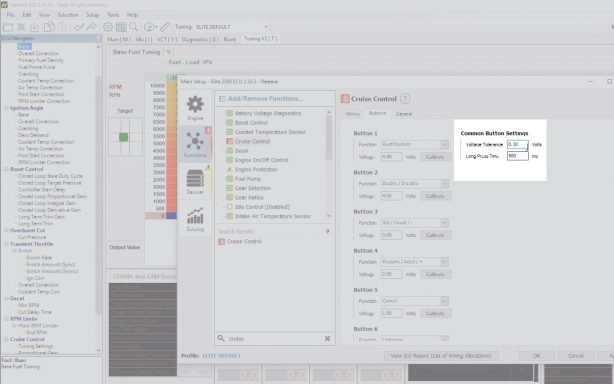
When a single button has multiple uses, (for example you may use the same button as the “accelerate” button as well as the “set” button) A long press can be configured. So when I set it up in the software I call it the set / accel / + button. A short button press activated the first function, which is set the speed and a long button press activates the second button function, which in this case is accelerate. Again on of the helpful things about ESP software is if you aren’t sure what a function or setting does, all you need to do is hover over the name of the setting and when that little question mark comes up click, and you will get a help bubble with a text description explaining what the setting does.
Once you have the system wired in and running, there is often some tuning of the system that needs to be done, which makes sense, a 200HP engine is going to respond very different to a 2000HP engine in the same vehicle.
To fine tune the cruise control we go over into the mapping tree on the left hand side of the tuning software and you will notice there is now a set of tunable maps for cruise control.
These settings allow you to set the maximum control system error value and the maximum throttle ramp in rate as well as mappable system proportion, integral and derivative gains.
While we do take time to setup and calibrate these PID settings in our base map, there are so many factors that influence the behaviour of the cruise control system some applications need these maps tweaked.
A little advice on calibrating the PID settings – Broadly speaking increasing the proportional gain will direct the control system to get to your target speed quicker,
Increasing the derivative gain will speed up the rate of change of the control system and increasing the integral gain will force the system to reduce the steady state error.
You will notice if you look at the base map settings for the proportional integral and derivative gains that the x-axis is actually based on the cruise control speed error,
As the vehicle approaches the target speed the system effectively pays less attention to the proportional and derivative gains – those are the two parameters that control how quickly and aggressively we try to hit your target speed – and more emphasis is placed on the integral gain which controls the steady state error of the system.
Thats its, thats the basics of how to wire in, setup and calibrate cruise control on your elite series ECU.
How Flex Fuel Control Works
In this article we are taking a closer look at flex fuel sensors. Topics covered are: what flex fuel sensors are, how they work, when you might need one and how to install and set one up on a Haltech ECU.
It’s no secret ethanol based fuels are becoming more and more popular with performance enthusiasts and for good reason. Ethanol has a high octane rating, it’s affordable, it’s renewable and it’s clean-burning.

On a high performance engine, burning ethanol as a fuel often allows us to run higher compression ratios, add more boost and increase ignition timing – all of which can help us achieve our ultimate goal of making more horsepower safely and turning on the WIN light at the end of the track.
What is ethanol and how is it different from gasoline as a fuel?
The chemical composition of ethanol is quite different to that of gasoline-based fuels. As a result of this, the volume of fuel required by an engine running on ethanol is about 35% greater than that of regular gasoline.

This presents a bit of a problem, because we have this new, clean, safe, powerful fuel available to us as performance enthusiasts, but it requires the fuel delivery system to be re-calibrated to deliver roughly 35% more fuel for it to work properly.

In the carburetor days that would have been a big issue because it would require re-jetting the carb completely for this fuel type, and, once that was done we couldn’t go back to gasoline without re-jetting the carb again.

With EFI however we can use a flex fuel sensor which, when installed into the fuel line, can measure the actual percentage content of ethanol in the fuel.
For example: if you had half a tank of gasoline and you topped the tank up with 100% ethanol then mixed it all around, you would end up with a mixture of 50% ethanol/50% gasoline.
The sensor would then read this 50/50 mix and feed that information into the ECU which can in turn be tuned to deliver precisely the right amount of fuel for that particular mixture of gasoline and ethanol in the fuel line. Or in carb speak, it’s like re-jetting the carb continually based on the amount of ethanol in the fuel.
Installing the sensor
Typically we install the flex fuel sensor in the fuel return line as shown in the diagram below. There are some of the limitations of installing it this way and we’ll get back to that later but for now let’s just agree this is the simplest and most practical place to install your flex fuel sensor.

Following the wiring guide that comes with the sensor, we wire up +12V, signal and sensor ground to the ECU wiring harness. Because flex fuel sensors are a frequency based input, this sensor needs to be wired into a digital pulsed input or DPIs on the ECU.

Software Setup
With the sensor installed let’s take a look at how to setup your Haltech ECU to read and use a flex fuel sensor.
The first thing to do is to go into the SETUP menu and click on MAIN SETUP. Go into the FUNCTIONS tab. The easiest way to navigate this page is to go to the SEARCH bar at the bottom and simply type “flex”.

Notice there are 2 types of flex fuel sensors commonly available. Haltech’s sensor allows you to read both ethanol content and fuel temperature from the same sensor so we click on the “Flex Fuel/Composition Sensor”.
When we enable this function we can see that the software prompts us to select an input we are going to wire the sensor to. In this case we have SPIs 1-4 available. Select one of these to let the ECU know which wire to look for the flex fuel signal on.

To use both the Ethanol Content and Fuel Temperature functions we will need to select the EDGE to rising.

Next, load the latest sensor calibration for both temperature and ethanol content by clicking on the LOAD CALIBRATION tab (that’s the one that looks like a folder).

Starting with the ethanol content calibration, select the “Fuel Composition Digital – Haltech” calibration.
Next, for temperature scroll down to the calibration named “Temperature_Digitalfuelcomposition – Haltech” and select it.
And that’s it. Your Haltech flex fuel sensor is setup and ready to use!

Setting Sampling Threshold
Remember how we said earlier that the best place to install a flex fuel sensor is in the fuel return line? While this is true in most cases, sometimes in high performance applications we might run into a problem of pushing the limits of the fuel pump to supply enough fuel.
When that happens, there is no fuel in the return line which can give some really strange readings on a flex fuel sensor.

That’s where Sampling Threshold settings can be used. Working on the theory that once the fuel is in the tank and the engine has ran for a minute or two, the ethanol content is fairly consistent until its refilled again, we can tell the ECU to stop sampling ethanol content above a predefined load and RPM to prevent incorrect sensor readings caused by lack of fuel flow through the return line.
Setting Fuel and Ignition tables
Once the sensor has been setup in the MAIN SET UP page, we are ready to start working with the fuel and ignition calibrations to ensure that the ECU delivers the desired amount of fuel for the actual content of ethanol in the tank.
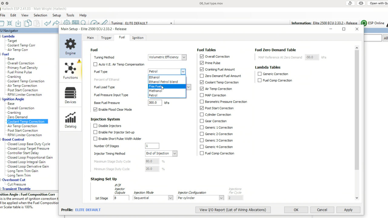
The simplest way of achieving this is to go into the MAIN SET UP window and click on the FUEL tab, here we can select the fuel type – select “Flex Fuel”.
This tells the ECU to look at the flex fuel sensor and automatically calculate the additional fuel required to provide the engine to meet the target air/fuel ratio.
This is where it gets interesting…
We know from the chemistry of the fuel type what the chemically and mathematically correct amount of additional fuel we need to add, but what we find in the real world is that by just adding the mathematically correct amount of additional fuel to the engine, the actual air fuel ratio as measured from the Lambda sensor in the exhaust is often out by a couple of percent.
There are a few reasons for this, but the most important one is the cooling effect that ethanol has on the incoming intake air.
This is actually one of the big advantages of using ethanol as a race fuel, cooling the intake air charge helps prevent detonation, which means we can run more boost and/or higher compression ratios.
Nonetheless, this non-linearity between theory and real world application means the ECU needs a way to correct for the difference between what should happen according to theory and what actually happens in the real world.
So when ‘Flex Fuel’ is selected as the fuel type, there is an additional ‘Fuel Scalar” table in the fuel maps. This Fuel Scalar table allows the tuner to correct the actual amount of additional fuel delivered vs the theoretical additional fuel required at specific ethanol content percentages.

The base map numbers that Haltech have in this map are a result of real world testing on a number of high performance turbo engines and for most forced induction applications they can be relied upon.
That’s the basics of flex fuel setup. Follow these steps and your engine will run the same regardless of how much ethanol you have in your fuel supply.
But wait, there’s more!
Let’s face it – you didn’t add ethanol to your engine to just run it the same as you always have. You really want to run more boost, more timing and make a bunch more horsepower when you can get your hands on this wonderful corn-burning octane of the gods.
Like with any function in the Elite series – now that the ECU knows the percentage of ethanol in the fuel you can use that data to control other functions.
Ignition Timing vs Ethanol Content
Go back to the SETUP – MAIN SETUP page and click on the IGNITION tab, notice here you can turn on a correction for “Fuel Composition Correction”. Turn this on and you get 2 new maps in the ignition maps.

There is that familiar ‘Flex Fuel Scalar’ table again and another table called the ‘Flex Fuel Correction’ table. Let’s first focus on the Flex Fuel Correction table.
This is the amount of additional timing you are adding over and above the base ignition map when you have 100% Ethanol (or more realistically E98 or even E85).
Once we have optimised this map for all load and RPM points on 100% Ethanol we don’t need to remap the entire engine at every 10% change in Ethanol content. Instead we go into the Flex Fuel Scalar tables and map in the ignition correction Percentage vs Ethanol Content.
For example, if we had 20 degrees of ignition timing in the base ignition timing map (that is the “no ethanol” tune) and 6 degrees of timing in the “Flex Fuel Correction” map then this scalar map calculates the percentage of the additional 6 degrees of timing to add based on the % of Ethanol content in the fuel.
Boost vs Ethanol Content
Its no secret that E85 allows us to safely run more boost in an engine, so it makes sense we may want to have our target boost increased with Ethanol content, or the other way of looking at it is we can reduce the amount of boost we are making when we cannot get E85.
Setting up Boost by Ethanol content is as simple as going into the “Boost Control” function again by pressing F4, finding Boost Control, clicking on the CORRECTIONS tab and turning on the “Flex Fuel Compensation” correction.

Now when we go to the Boost Control maps we have a new table under the CORRECTIONS heading of “Flex Fuel”.
This map axis is based on the percentage of Ethanol in the fuel and gives us the ability to add more boost with Ethanol content. This table is additional boost to whatever value you have in the regular boost control target table.

Ethanol Content vs Anything
Because Haltech Elite series ECUs have flexible map axis and now the ECU knows the Ethanol content you can use this information to map any number of additional corrections.

For example, we know that engines running on E85 require more fuel on startup when they are cold.
That’s because ethanol has a higher fuel distillation temperature than gasoline, so something we might want to do is go into both Fuel Prime Pulse and Cranking Correction maps and add Flex Fuel Percentage as an axis to these maps.
Don’t do this!
Don’t turn on the “Flex Fuel Composition” correction table in the Fuel Corrections. If you have set the fuel type to “Flex Fuel” typically you DO NOT use this map.

This map is only used when the fuel type is set to “Petrol” and it exists so that our existing Sport Series ECU customers could import their old ECU maps directly into an Elite series ECU.
Turning this map on with the fuel type set to “Flex Fuel” will give you a double correction.
This is a common mistake that we see people making so don’t fall into this trap as well.
How Turbo Boost Control Works
Turbos, boost, and horsepower go hand in hand – but only if you’re in control of the turbocharger. In this article we cover the basics of turbocharging and boost control.
How a turbocharger works
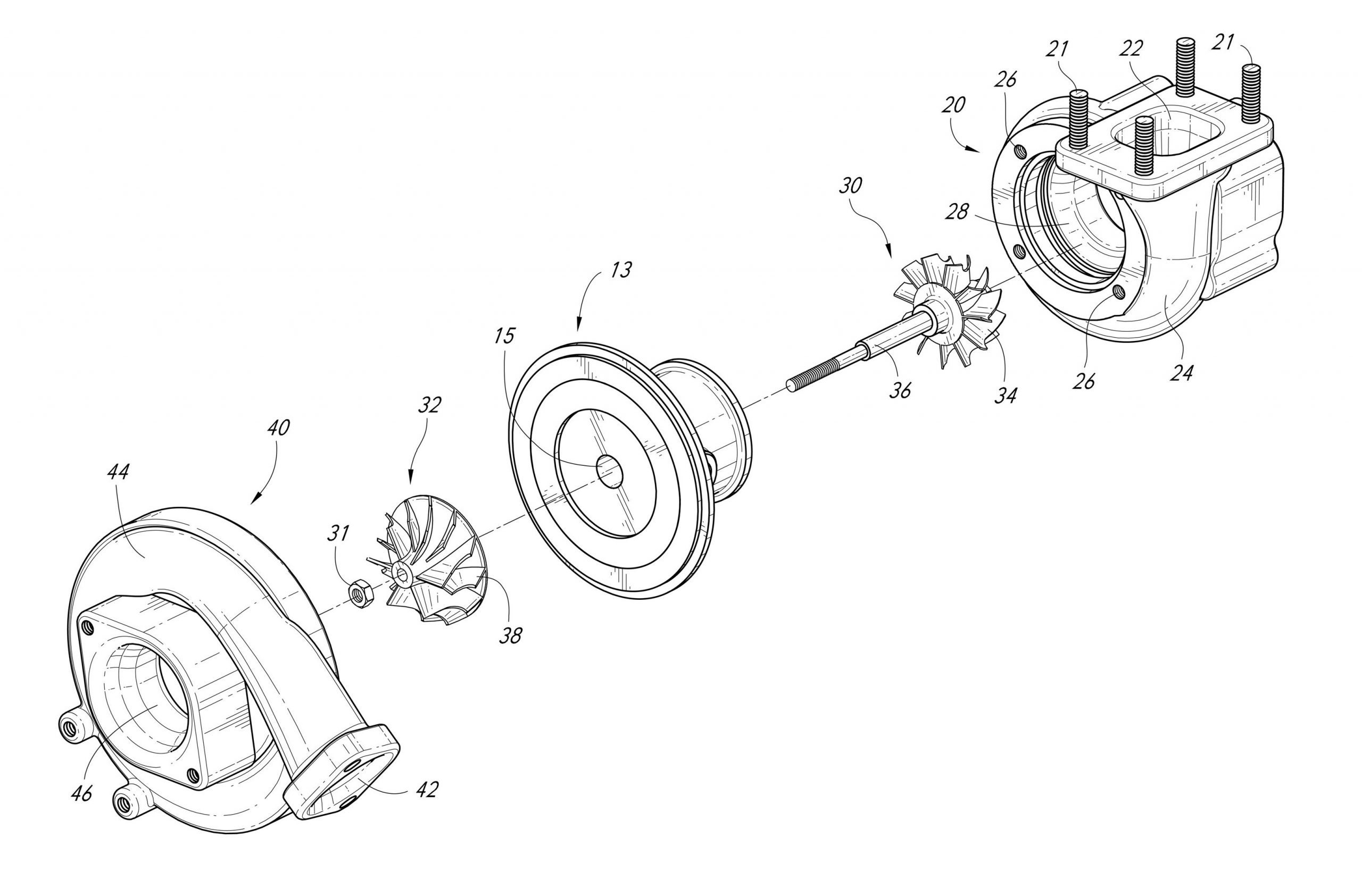
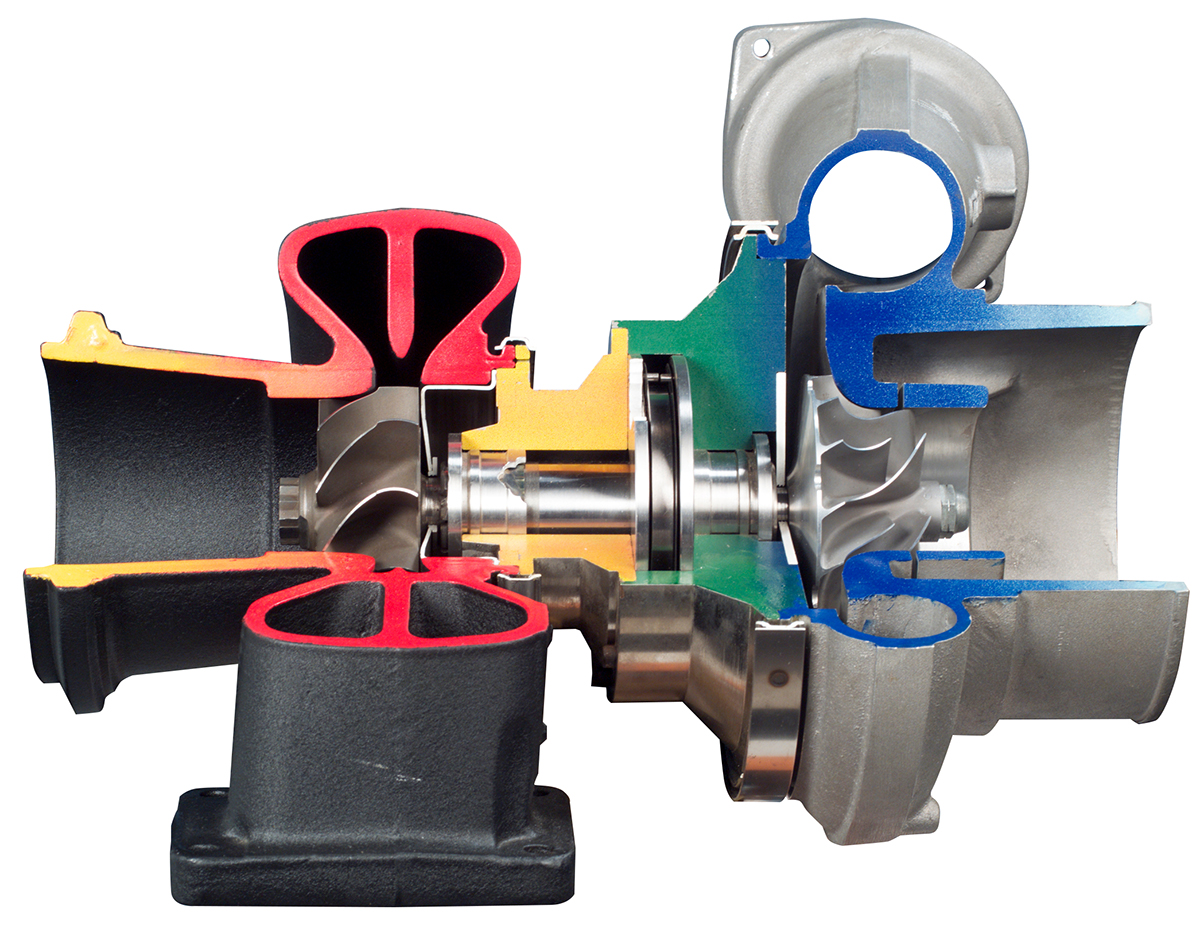
In order to understand how boost control works we first need to understand how a turbocharger works. A turbocharger uses engine exhaust gases to spin up a turbine wheel (30), which is mounted on a common shaft (36) with a compressor wheel (32). The faster you spin the exhaust wheel the faster the compressor wheel will spin.
The Compressor wheel (32) pulls fresh air through the air filter (46) and jams it into the engine (42), resulting in what we know as Boost Pressure.
Why does boost pressure make a difference to engine power?
The more compressed the intake air is – the more oxygen-dense or heavy it is, therefore the more oxygen you can get into an engine – the more power it’s going to make. Of course there are limits. You can’t just put unlimited boost into an engine, you need to regulate the speed of the exhaust turbine wheel and in turn regulate the speed of the compressor turbine wheel.
This is achieved by bypassing exhaust gasses around the exhaust turbine wheel with a component known as a Wastegate.
How a wastegate works
As the name suggests a wastegate “wastes” engine exhaust gasses by feeding them directly into the exhaust system and around the exhaust turbine wheel. The wastegate uses a boost referenced, spring-loaded diaphragm in order to determine just how much exhaust flow should be directed around the exhaust turbine wheel and how much should go through it.
It seems odd to waste all this energy but there are good reasons for that. The turbocharger assembly spins at over 100,000 RPM and it’s important to regulate the exhaust gasses to make sure it doesn’t over-spin resulting in a catastrophic failure.

It’s also important to regulate the exhaust side to control the intake side. When we have control over the speed of the compressor we effectively have control over the boost pressure.
That’s just mechanical boost control. With electronic boost control we can have different boost pressures at different Engine RPM or depending on the Ethanol content of the fuel, or via a simple boost switch on the dash. There are endless combinations of boost control strategies you can employ to make the most effective use of the boost generated by your turbocharger.

Sensing Boost
In order for the ECU to control the boost pressure it needs to measure the boost pressure – for that we use a Manifold Pressure Sensor. This sensor’s mounted after the throttle body but before the intake valves and measures the pressure in the intake manifold. We also need a boost control solenoid. We use this solenoind to manipulate the amount of boost pressure the wastegate sees. The more pressure we bleed off, the more exhaust gasses the wastegate will direct through the turbine wheel resulting in more boost pressure.
In the ECU we can set our Boost Target against numerous parameters like Engine RPM and Ethanol Content. Let’s say when we’re at 85% Ethanol and 6000RPM we want 20 PSI of boost pressure – the ECU will pulse the boost control solenoid directing the pressure between the wastegate and out to atmosphere in a delicate balancing act to achieve our target boost into the engine. Because exhaust flow isn’t consistent across all RPM and engine loads the boost control solenoid has to do plenty of work in order to manipulate the wastegate and achieve the target boost pressure.
So next time you put your foot on the throttle and feel the boost come on – spare a thought for your wastegate, the environment it’s working in and how hard it’s working to control your boost!
Dyno Tuning Basics
Ever wondered what happens when your tuner puts your car on a dyno? In this article we lift the veil on the black magic of Dyno Tuning.
Types of Dynos
There are three main types of Dynamometers, an Engine Dyno, a Hub Dyno and a Chassis Dyno. Each with its own set of benefits and drawbacks.

An Engine Dyno is great for getting very consistent results in very consistent conditions. The engine is removed from the car or put straight on the engine dyno after being built and connected directly to the dyno load cell (with no gearbox).
The engine dyno’s water cooling supply, fuel system and sometimes ignition system would be connected to the engine and it would be started and ready to tune. This is often a very time consuming task and better suited for engine development programs or an engine that would be modified over several weeks or months.

If you don’t want or need to remove the engine from your car, a Chassis Dyno is a more practical option. A car’s driven straight off the street, strapped down to the rollers and is ready to be tuned.
This is certainly the fastest way to get tuning, but it does have its drawbacks. The car is strapped into the rollers using a method where the harder the car wants to pull forward the more the downwards force increases. This results in the car pulling harder down into the rollers.
This works really well and provides consistent results – up to a point, after which you end up fighting the traction limit of the tyre. This limit is normally around 800-1000hp depending on a car and/or the dyno setup.
The chassis dyno is ideal for getting cars making up to around 800hp on and off quickly with minimal setup time.

Then, we have the Hub Dyno, which is bolted directly to the vehicle’s drive hubs, eliminating the wheels and tyres altogether. This is a great solution for high powered race and street cars and a great “in the middle” solution between Chassis Dynos and Engine Dynos.

You can have accurate, repeatable results in cars that are making well north of 2000hp, or you can fine tune a 400hp street car. The downside is there is a little more setup time involved than in a Chassis Dyno and each vehicle’s stud pattern and rear end length may need a different adaptor to bolt onto the dyno.
How Dyno works
Regardless of the dyno style, it needs to perform the following functions:
• Measure the retarder speed. (from a speed sensor found on the roller shaft)
• Control the rate at which the retarder shaft spins.
• Measure the load at the retarder arm. From a load cell found mounted between the retarder and the dyno chassis. This mechanical connection is the only thing stopping the retarder from pivoting forward, and the only thing that’s measuring how hard the retarder is being forced against the dyno chassis.

In order to control the rate of acceleration of the roller, or to hold a particular roller speed there is an “Eddy Current Retarder” attached the end of the common shaft that the car is sitting in. There is typically one or two for each bed, more retarders means more muscle to hold more power! Our particular dyno has one retarder per bed.

The eddy current retarder is commonly found in roller coasters and train brakes and works by applying a specific amount of electrical energy into the unit in order to provide the required amount of resistance or braking force. The result of this effort is heat, which the retarder disperses with its own internal fan like design in order to keep the retarder core temperature to a minimum.
Because we know the roller speed and we know the force being applied to the load cell we can calculate the amount of Horsepower generated using a fancy formula which is:

So what does it all mean? On our Chassis dyno it means we can hold a car at any consistent road speed and any engine load in order to measure the power output and adjust the engine management system until the engine is making the most power at that point – this is known as “Steady State Tuning”
We can also do a ramp test allowing the engine to go from 2000RPM to 7000RPM over 15 seconds, essentially choosing how many meters or feet per second the dyno will allow the engine to accelerate at. This is known as a “Power Run”
With the Steady State Tuning done, we can then adjust the engine management parameters at all load and RPM sites in order to make the most power at each RPM and Engine load.
Why you need a Fuel Pressure Regulator
A modern port fuel-injected engine has an electric fuel pump that feeds fuel from the fuel tank, up to the front of the car and through the fuel rails (which house the fuel injectors), through the fuel pressure regulator, then back to the fuel tank.
What’s the job of a Fuel Pressure Regulator
A fuel pressure regulator’s job is to maintain a consistent fuel pressure across the fuel injector by regulating how much fuel’s returned to the fuel tank in order to maintain the desired fuel pressure. The important thing to note is the fuel pressure needs to be consistent ACROSS the fuel injector not just at the tip.
A typical “base” fuel pressure is 3 bar or about 45psi which means that if we measure the pressure up the backside of the injector we’re going to see 45psi. Knowing that we can then determine the fuel injector flow rate. For Example, an injector commonly referred to as a “Bosch 1000” actually flows 1035cc at 45PSI and 1085cc at 50PSI. So that difference in “base” fuel pressure makes a difference to the amount of fuel the injector flows.
Why is that important? Most modern ECUs work by calculating the amount of air going into the engine at any given time, then adding the right amount of fuel in order to achieve the tuner’s desired Air to Fuel Ratio. If the ECU has been told the wrong injector flow rate, the engine’s fueling and fuel corrections won’t be accurate and the tuner will have a hard time getting it right.

Don’t forget the Manifold Pressure
A huge factor here that’s often overlooked is the Manifold Pressure. If you have 45PSI of fuel pressure going up the backside of the fuel injector and 10PSI of boost pressure acting against the tip of the injector – you’ll end up with a “Differential Pressure” (or pressure across the injector) of 35PSI.
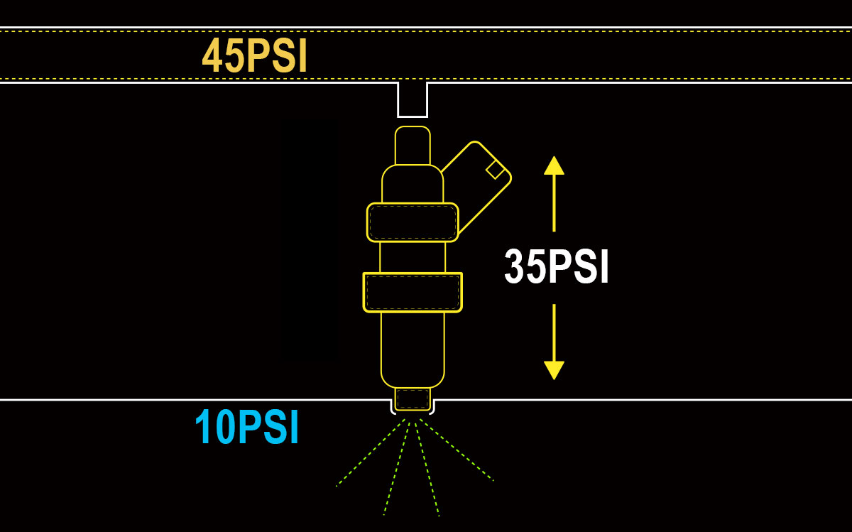
This means that all the fuel calculations would then need to work off an injector flow rate of 35PSI, not the 45PSI we had when we set the base fuel pressure. This is where a Manifold Pressure Referenced Fuel pressure Regulator comes in handy.

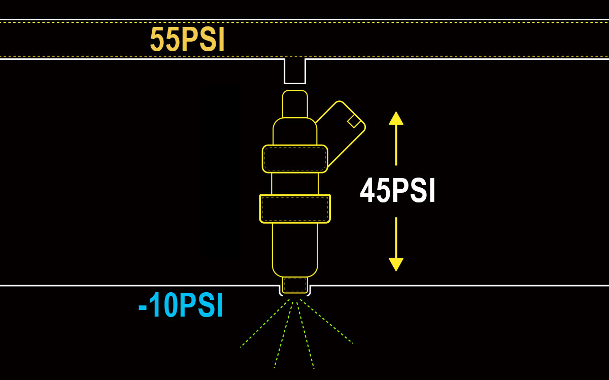
We use the Manifold Pressure Reference to maintain a consistent “Fuel Pressure Differential”. This way, when we put 10PSI of boost into the engine the fuel line pressure is INCREASED by 10PSI resulting in a fuel line pressure of 55PSI and a differential fuel pressure of 45PSI – the same as what we started with and resulting in the same injector flow rate, even though the fuel line pressure and the pressure acting on the tip on the injector has changed.

The same Fuel Pressure Regulator also works in reverse, when the engine is idling in vacuum, the base fuel pressure will be reduced to maintain the pressure across the injector because the vacuum in the inlet manifold is sucking the fuel out, resulting the same injector flow rate but with less fuel pressure.
NOTE: The Base Fuel Pressure should be set with the fuel pump running and the vacuum hose disconnected from the fuel pressure regulator.
You can also map your Fuel Injector Flow Rate vs. Your Differential Fuel Pressure, that way if there are any discrepancies in your fuel system the ECU will always know exactly how much fuel your injectors are capable of flowing.
How relays work and why you need one
In this article we are talking relays. Often misunderstood, relays are among some of the most integral components of your car’s electrical system.
A power relay is used when a high current device like a fuel pump or a thermofan needs to be triggered from a low current output like an ECU or a dash-mounted switch.

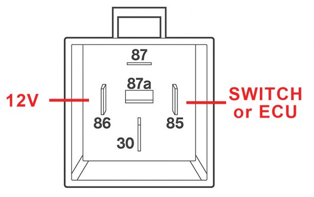
Power relays are available in a huge range of configurations for an even bigger range of applications, for this article we will concentrate on a simple 4 pin relay.
As the name suggests the relay has 4 pins. Inside the relay we will find two circuits – one for low and one for high current. The low current circuit’s job is to switch the high current load on while drawing the least amount of current possible.
To do this 2 pins are needed:
PIN 86: This should be connected to a 12V supply which turns off when the cars ignition is turned off and normally draws only around half an Amp of current.
PIN 85: This should be connected to the ECU or a dashboard switch and should pull to ground when switched or activated.
Note that we are switching the ground on and off to trigger the relay? This is most common in the automotive industry but you can also supply constant ground to Pin 85 and have the switch supply power to Pin 86 if that is how your wiring is already done.
Now to the high current side.
PIN 30: This should be connected to the battery through a fuse and should be capable of supplying whatever current the load (the fan or pump) requires. This could be 10, 20 or more than 30 Amps depending on the device. Make sure to use the correct gauge/thickness of wire and correct fuse size.
PIN 87: This is the supply output to the device, ie the power supply to the fan or pump. Your wiring will need to support the same current as Pin 30.
The device will then be grounded to the chassis and again, you will need the right wire gauge to support the high current load.

How does it all work?
Pin 85 and 86 are connected to a coil of wire which is wound around a little iron core. When you apply power to a coil like this it makes a little electromagnetic field.
When that electromagnetic field is present an “Armature” capable of carrying high current connects Pin 30 and 87. When the electromagnetic field is de-energised the armature naturally opens causing the circuit to open and consequently the device to turn off.

So there you have it. If you need to activate a heavy load, high current device using a small, light load switch – you will need a Power Relay!
Extra Sensory Perception
How many sensors are required in order to run an aftermarket ECU and what are they? While there are many additional sensors you can fit to further increase the functionality of your ECU, there are some that are essential for ECU to run the engine successfully.
Your Haltech engine management system relies on the following sensors to run the engine:
• A Trigger, or Reference Sensor. This sensor tells the ECU how fast the engine is turning and possibly what angle the crankshaft is currently at.
• A Home or Synchronisation Sensor. This sensor tells the ECU exactly what position and which stroke each piston is up to.
• Manifold Absolute Pressure Sensor (or MAP Sensor) Used to measure the amount of pressure in the Intake manifold, this sensor could be mounted directly on the intake manifold or remotely mounted with a vacuum hose.
• Air Temperature Sensor. This sensor lets the ECU know the temperature of the air entering the intake manifold, its normally found close to the throttle body either just before or just after it.
• Coolant Temperature Sensor. This sensor measures the temperature of the fluid in the cooling system which is representative of the engine temperature.
• Throttle Position sensor (TPS) Measures the throttle body blade angle and it is used to trigger Throttle pumps or deceleration fuelling conditions to improve fuel economy.
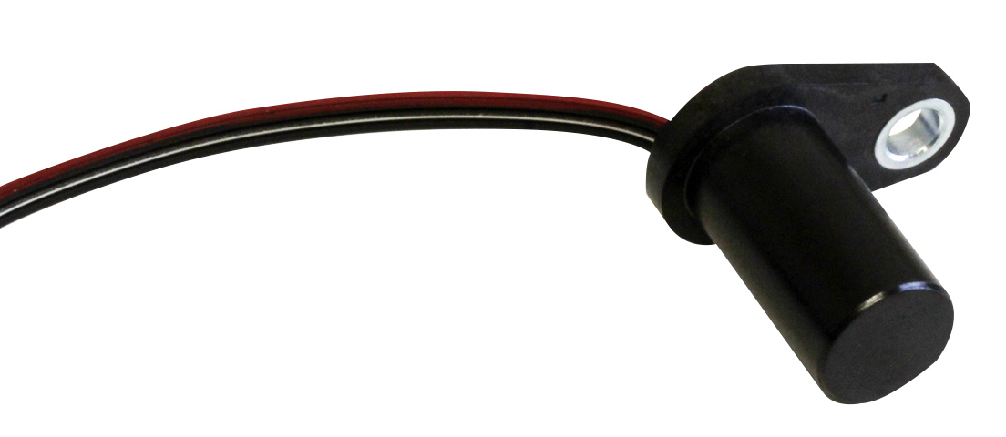
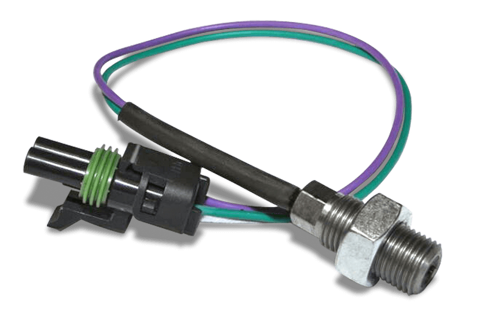

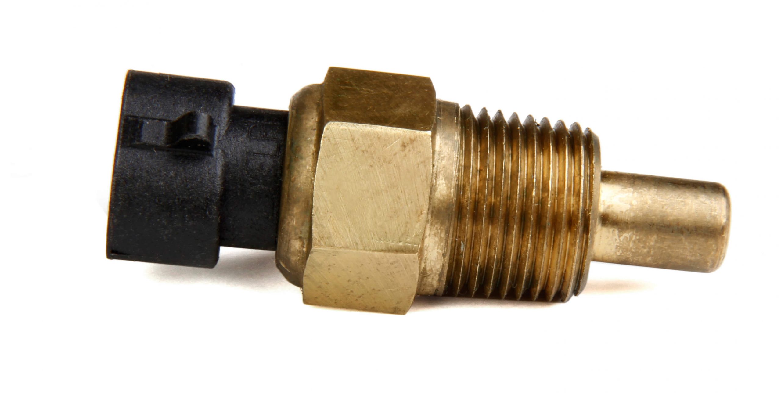
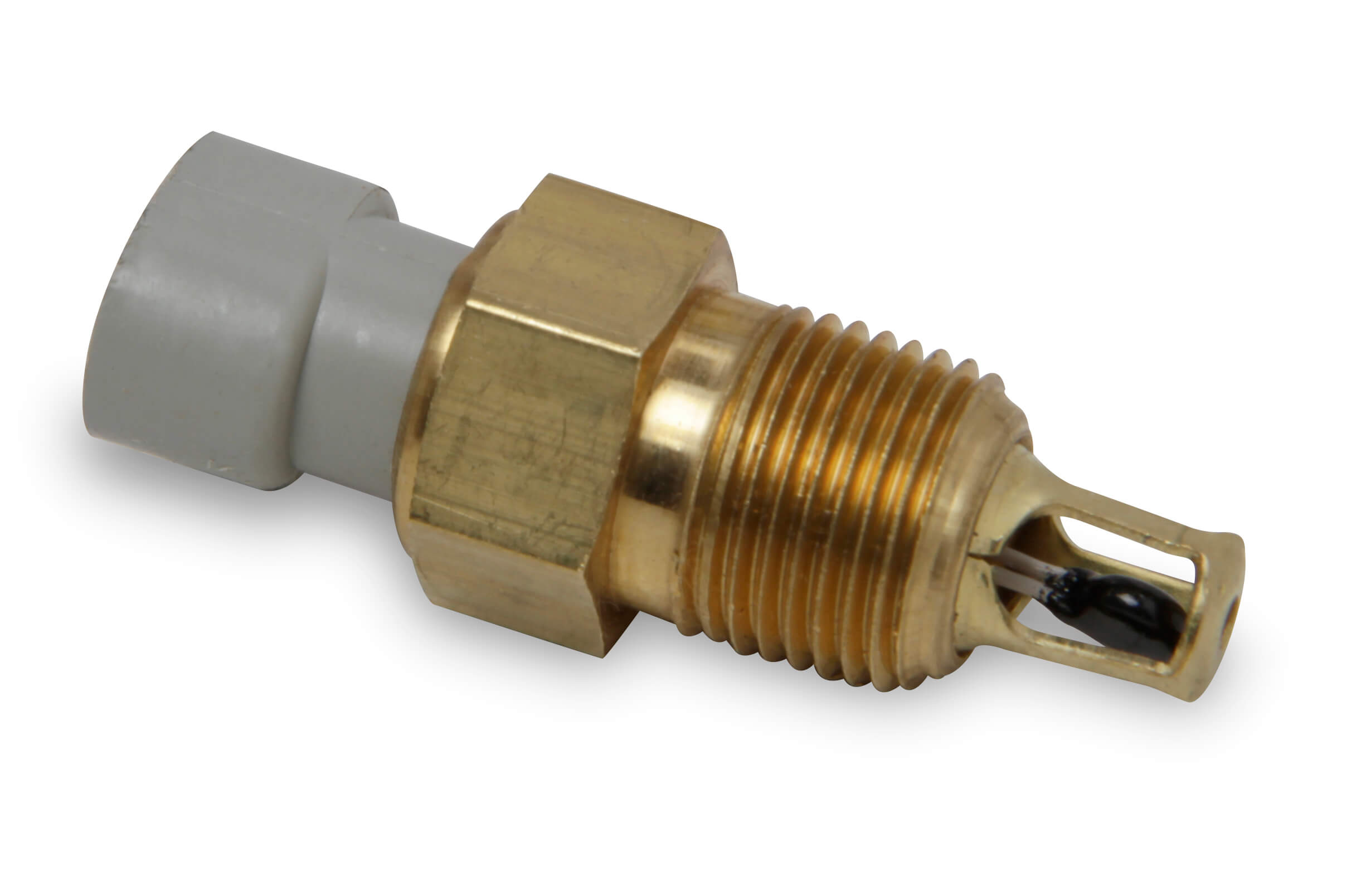
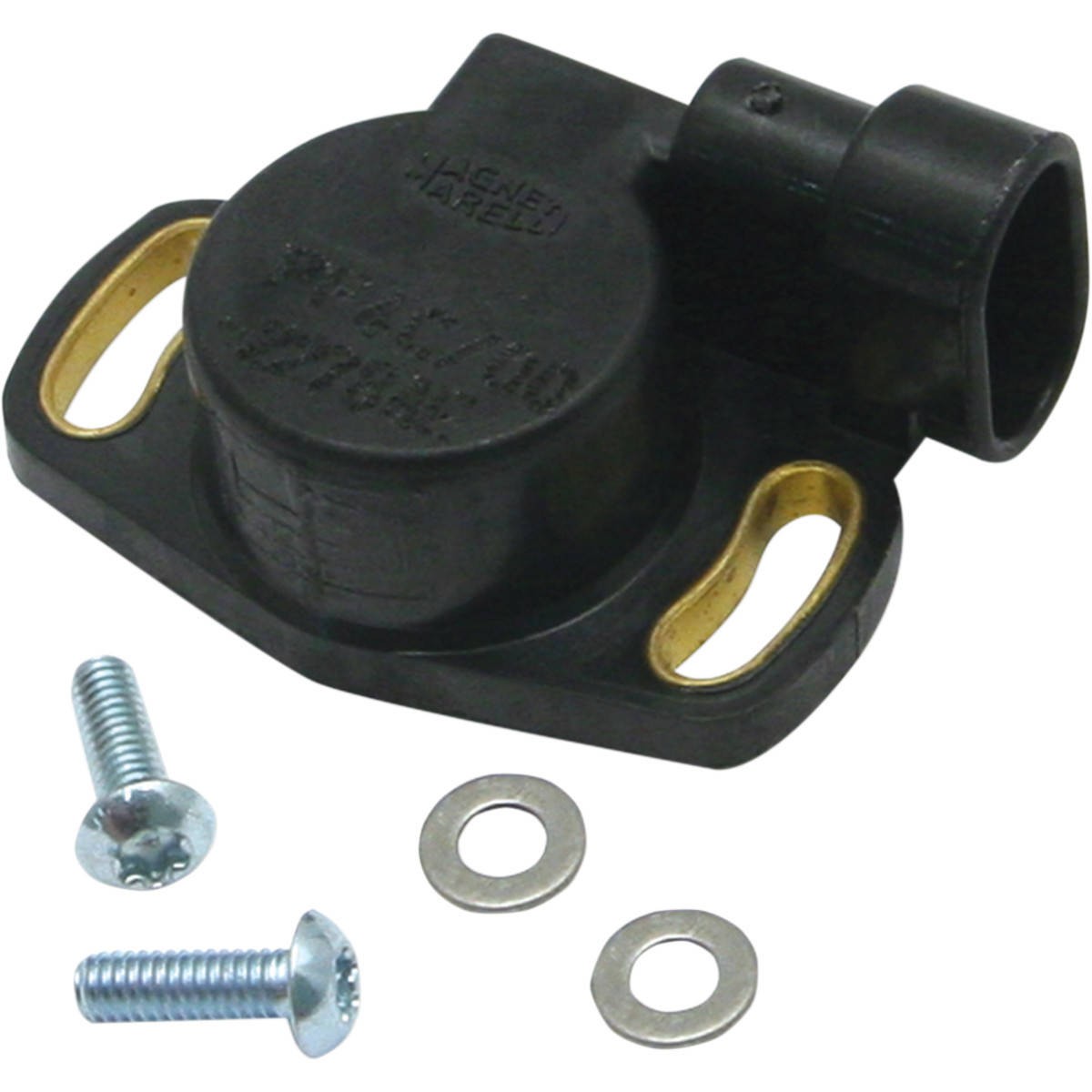
Just the basics
The Manifold Pressure, Air Temp and Coolant temp sensors work together to give the ECU an accurate estimation of the “Charge Air Temperature” which is the temperature of the air entering each cylinder. With this information, the ECU can then determine the mass of air entering the cylinder, then inject the right mass of fuel in order to achieve the correct Air to Fuel Ratio (AFR).
You can map fuel and ignition corrections against the Air and Coolant temperature sensors, this can aid with cold starting, re-starting once the engine is warmed up, or adding a level of safety to the tune.
The Manifold Pressure sensor, while primarily being used as an engine load sensor is also used in the boost control function. This sensor allows us to request a specific boost pressure and let the ECU’s boost control strategy chase after it. It can also be used to limit the boost pressure in the case of a wastegate or hosing failure.
But wait, there’s more…
The above list covers the critical engine running sensors that should be included in a basic EFI setup. There is a plethora of other sensors that can be used for extra mapping functionality, engine protection, data-logging and to transmit to dash displays.
Among those, the most popular are:
• Wideband Oxygen Sensors
• Ethanol Content Analysers
• Fuel Pressure Sensors
• Fuel Flow Sensors
• Oil Pressure Sensors
• Oil Temperature Sensors
• Coolant Pressure Sensors
• Exhaust Gas Temperature Sensors
• Wheel Speed Sensors
• Driveshaft Speed Sensors
• Turbine Speed Sensors
• Suspension Travel Sensors
Nissan CAS – Facts and Fiction
One of the most hotly debated topics within the global RB community is the accuracy of the Nissan OEM Cam Angle Sensor (CAS). In this article we will attempt to separate facts from fallacies, explain the cause of the problem and recommend a solution that could not only save you costly repairs but help you make the most out of your RB engine.
How Nissan’s CAS works
Nissan’s RB CAS is an optical sensor located on the exhaust camshaft gear. Its job is to read both the engine speed and the piston/stroke position and relay that information to the ECU which then uses it to calculate and deliver Fuel and Ignition events.
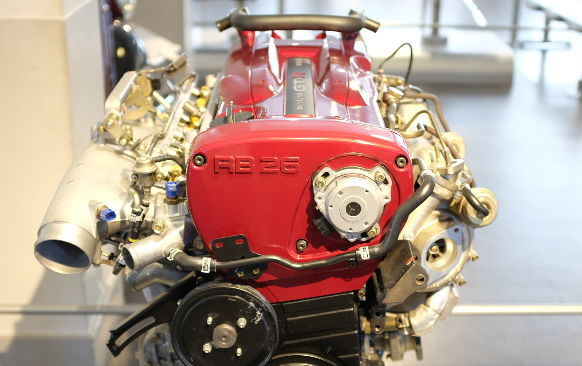
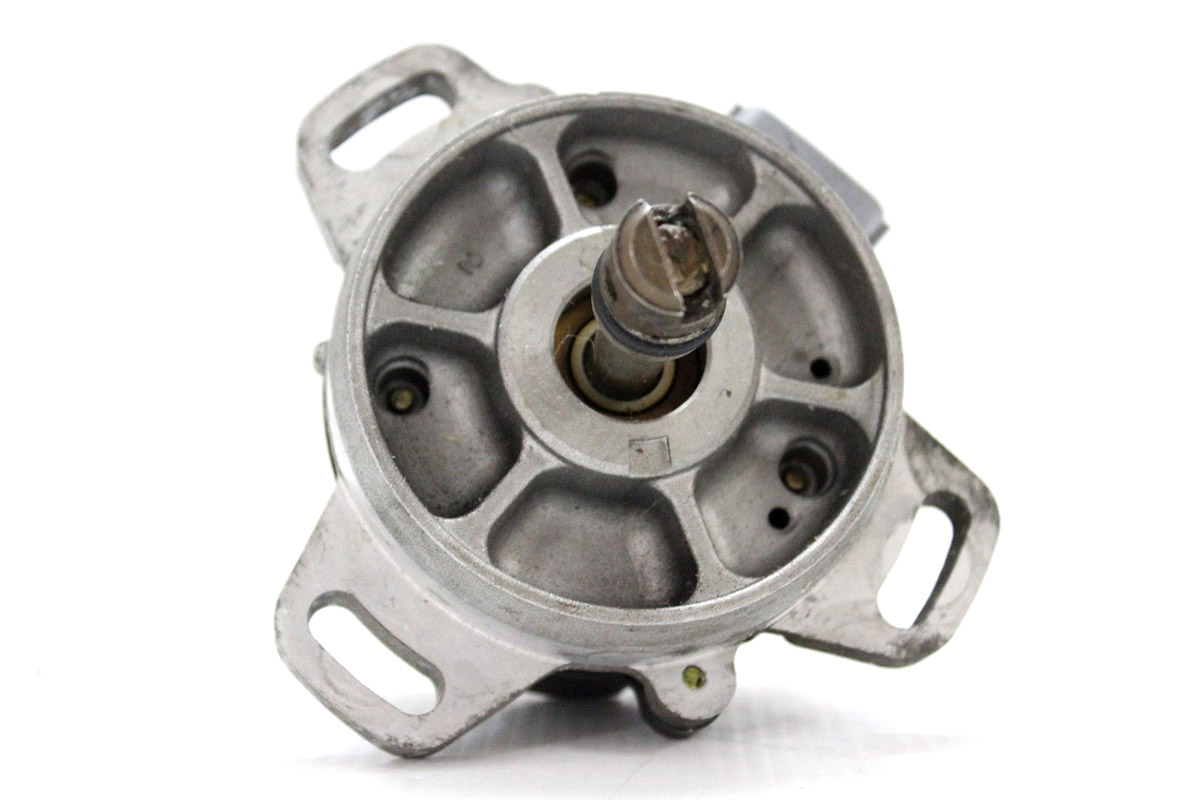
Potential Problems
The main shortcoming of this system is its reliance on the single CAS to measure both engine speed and engine position. Because the camshaft is linked to the crank via a timing belt, any distortion in the timing belt will result in an inaccurate crank angle position being delivered to the ECU.
When inaccurate data is then sent to the ECU, it will make ignition and fuel calculations based on that inaccurate data and as a result, the injector and ignition timing accuracy will be compromised. Just how much timing belt deflection can you expect on an RB engine? On a stock, unmodified engine it may be barely noticeable but once you start adding mods and increasing power levels, the belt deflection will increase dramatically. We have seen up to 8 degrees of cam belt deflection in 700kW RBs. That’s quite a lot!
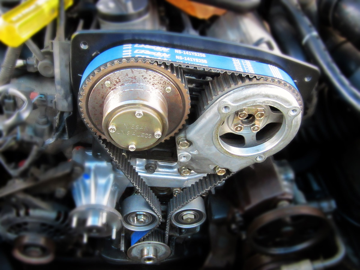
The solution
Fortunately, there’s a simple solution to this problem and that is to replace the OEM CAS with a cam and crank sensor kit. How does this help with the belt deflection issue? By splitting the OEM CAS into two separate units, the cam shaft sensor is used solely as a home signal with the crank position sensor providing the cylinder/stroke information. Aligning the cam signal with a gap between the teeth on the crank gear allows plenty of room for the belt deflection and effectively eliminates any negative effects caused by it.
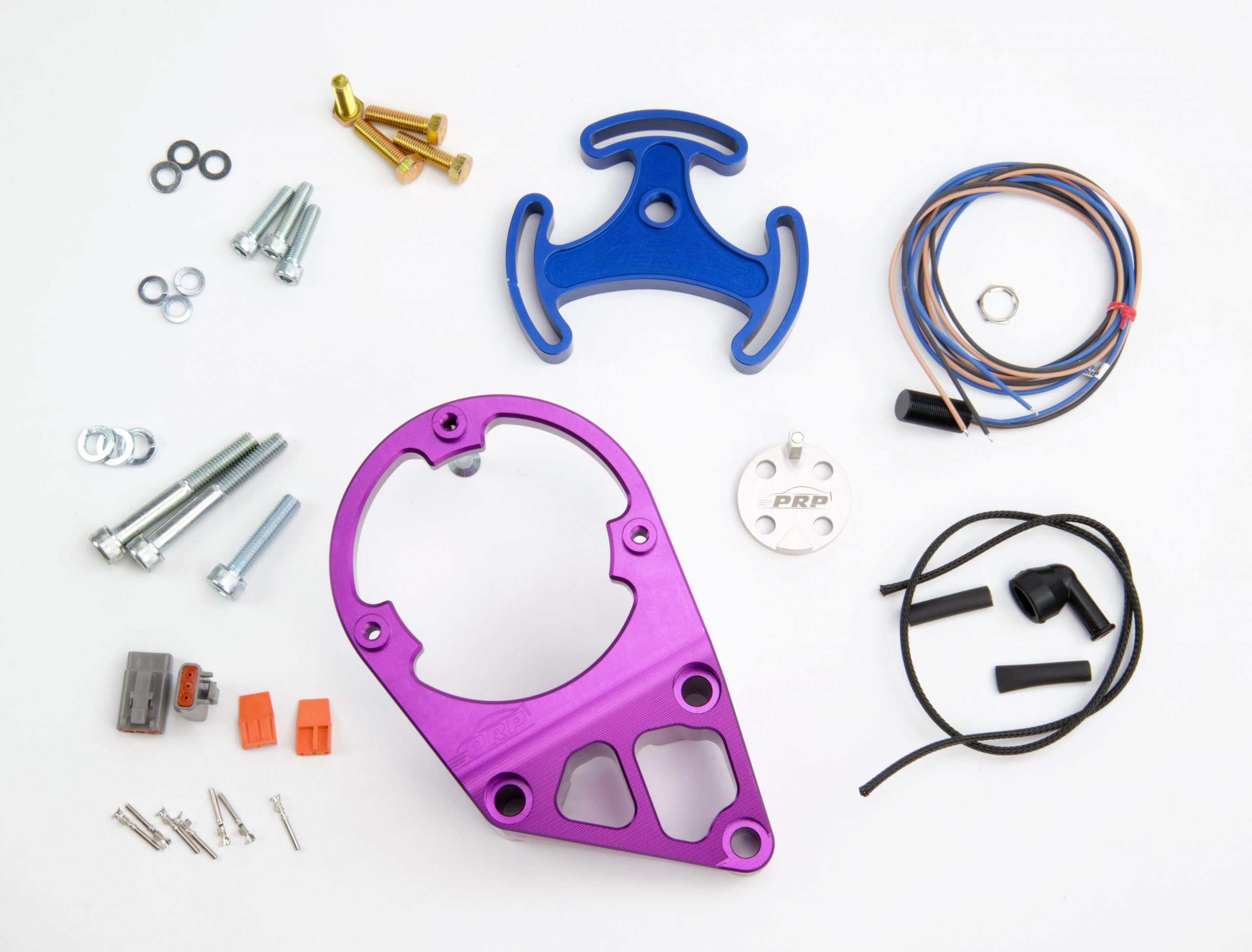
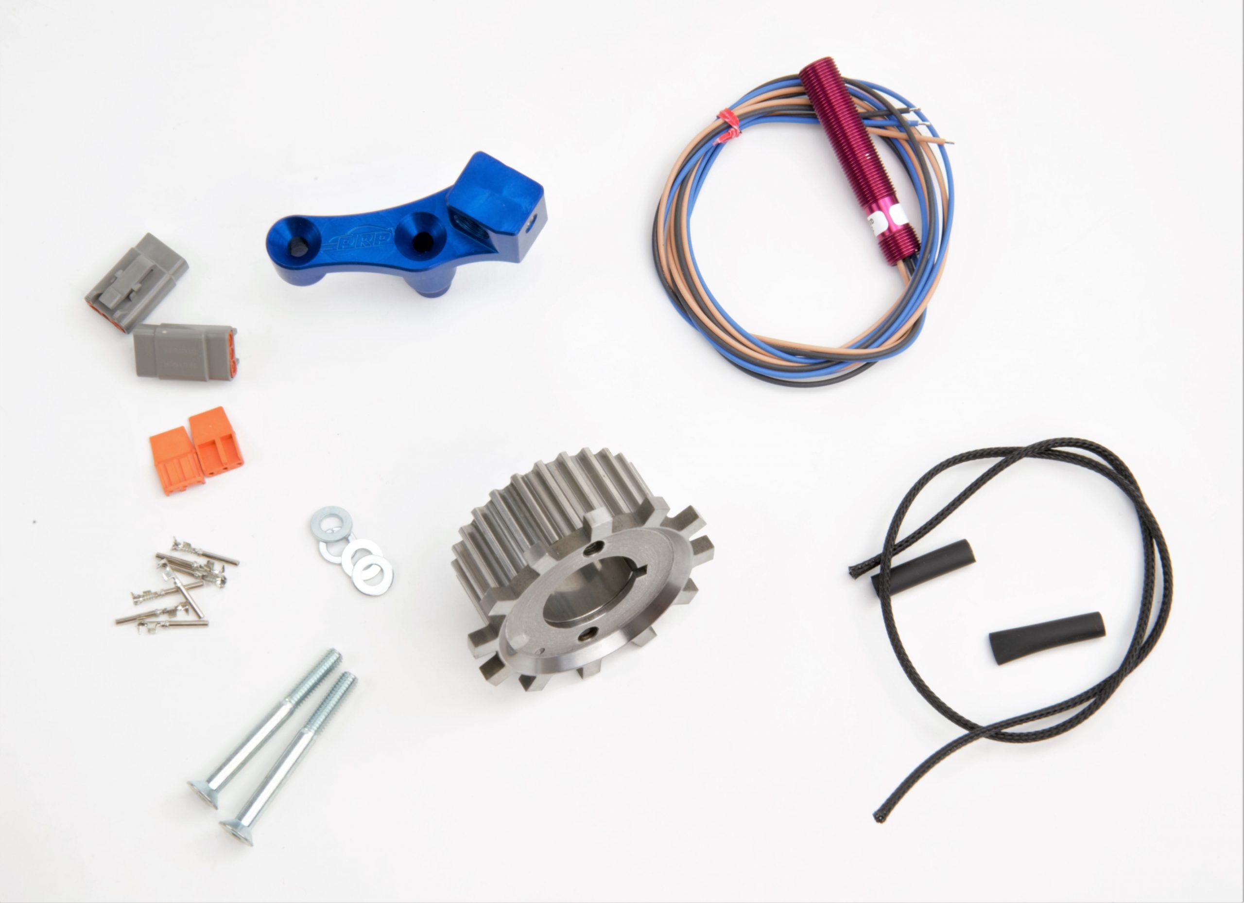
Is it only applicable for high horsepower cars?
While the belt deflection certainly has a greater effect on modified, high power engines, fitting a crank angle sensor kit to low and moderate power RBs will still pay dividends with more reliable, accurate signal and thus a better, more efficient tune.
Matching your sensors to your gears
It’s important to choose a correct sensor for your cam and crank gears. Your decision on using a Reluctor type or a Hall Effect type sensor will depend on the number of teeth on the cam or crank gears.
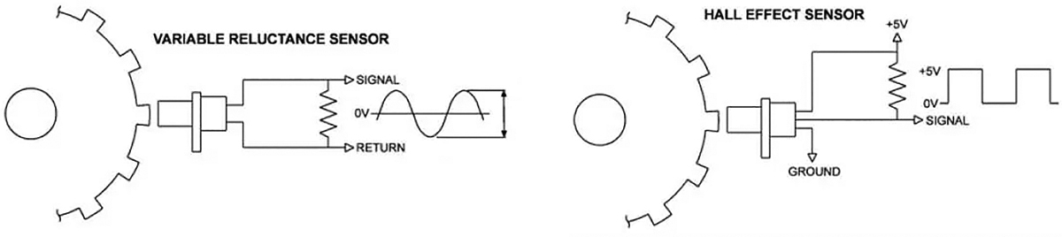
How ECUs Work
In this article we go back to the basics and explain what an ECU is and how it works.
An ECU is a computer designed to control ignition and injection in an engine. It plays a central role in an EFI system, much like a carburetor and a distributor did in an old-school, mechanical system.

Like any computer, an ECU has a bunch of inputs and outputs. Inputs are connected to a wide array of sensors on the engine which provide the ECU with essential engine information.
The most basic sensors needed for an engine to run are:
• Air Temperature
• Coolant Temperature
• Throttle Position
• Manifold Pressure
• Engine Speed
Once the sensor information is received and processed using a fuel and ignition table, signals are sent out via the ECU’s outputs to the fuel and ignition system.
Basic ECU outputs will control:
• Fuel Injectors
• Ignition Coils

The outgoing signal tells the injectors how much fuel to provide in order to achieve the desired air-to-fuel ratio. It also tells the ignition coils when to fire in order for the spark to occur at the right time.
Tuning or Calibrating of an ECU is usually done via an external computer and involves setting up a “Lookup Table”. This table normally will have a load (RPM) axis and a throttle position or manifold pressure (load reference) axis. With these a tuner will be able to map ignition timing and the amount of fuel needed at each interval. Once completed, these tables will allow an engine to operate at its optimum under a wide range of conditions.

Haltech provides “Base Maps” for many popular engines. A Base Map will allow you to start and run that engine with a basic set of perimeters. It can then be fine-tuned to your particular application and needs.
Of course this is just the very basic explanation of the most essential ECU functions. Advanced aftermarket ECUs like the Haltech Elite series offer many additional functions and features that are made possible by utilising all available inputs and outputs on the ECU.

By adding sensors to monitor fuel pressure, oil pressure, exhaust gas temperature and fuel pressure you can activate various levels of engine protection. For advanced racing features like launch control or torque management you’ll need shock travel sensors and drive shaft speed sensor.

On the output side you can add various accessories like thermo fans, shift lights, tachos or variable cam control.
Modern aftermarket ECUs offer infinite tuning possibilities with a range of features and functions available at a tuner’s disposal. While most will perform the same basic job of controlling your injection and ignition, some will have functions specifically designed for one particular type of motorsport ie drag racing.

When choosing your aftermarket ECU it is important to first decide what features and functions are important to you. We cover this in another article: Which ECU is right for YOU?
Haltech’s Advanced Torque Management – More Grip, Less Slip!

Aimed at drag racing professionals, Advanced Torque Management is Haltech’s brand new engine management feature that promises to reduce the loss of traction and tyre shake, making aborted passes a thing of the past.

Haltech’s Advanced Torque Management eliminates the impact numerous variables like the surface condition or temperature can have on the car’s performance providing consistent, repeatable results.

How does it work?
A Driveshaft RPM sensor monitors the Driveshaft RPM and reports back to the ECU. The Driveshaft RPM is then used as a target in the Torque Management tables. If the Driveshaft RPM goes above or below the target Driveshaft RPM, the ECU immediately adjusts the tune to compensate and bring the Driveshaft RPM back to its pre-set target.

As well as Driveshaft RPM, Haltech’s Advanced Torque Management can also be mapped against Wheel Speed or Engine RPM. Multiple profiles can be set up and triggered by a sensor input or a dashboard switch panel.
How does it help you go faster?
The benefits of having full control over your torque are many and varied, the most obvious one being consistency. Changing track conditions, temperature or environmental factors can all cause loss of traction often resulting in aborted runs.

With Haltech’s Advanced Torque Management every run counts and every run delivers consistent results. If there is one thing all seasoned drag racing pros agree on it’s that consistency equals lower ETs.
How to get Haltech Advanced Torque Management?
Haltech Advanced Torque Management is available on the following products:
• Elite 2500T
• Elite 2500 (with a 2500T upgrade)
• REM (Race Expansion Module)

For more information contact:? [email protected]
or call: 760 598 1941 (Nth America) or +61 2 9729 0999 (Australia, Europe, Asia and Africa)

Elite 2500T (DBW + Advanced Torque Management)
Applications:
• 1 to 12 cylinder engines
• 1 to 4 rotor engines
• Normally aspirated or forced induction
Features:
• Waterproof Case (IP67)
• Torque Management Functionality
• 8 x Fuel Injection Outputs
• 8 x Ignition Outputs
• 28 x Digital Outputs
• 10 x Analogue Voltage Inputs
• USB Laptop Communications up to 1 MB/s
• 6 x Engine Position Inputs with extensive trigger type support
• Programmable Injector Peak and Hold Currents
• OBDII Capable – Set and clear diagnostic trouble codes, view live engine data
• ESP Calibration Software – Intuitive and easy to use
• Dual CAN Bus communication for OEM and Haltech CAN Expansion
• User definable 5D Tuning – Tune by gear, Cam angle or any channel for ultimate flexibility
• Variable cam control – Independently control up to 4 camshafts Auto tune capabilities –
• Short and Long term fuel, ignition, boost and idle control learning
• Dual Channel Knock Control – with high speed digital filtering for accurate detection
• Multi-fuel Support – Support for Petrol (Gasoline),LPG, Methanol and Ethanol
• E85 Flex Fuel Ready – Direct connection to sensor.
• Closed Loop Boost Control – Multiple Modes – Tune by gear, wheel speed or time
• Closed Loop Idle Control – With learning for consistent idle stability
• Closed Loop 02 Control – Dual bank control for precise tuning
• Anti-Lag and Launch Control – Drag and Rally modes
• Data logging – Up to 40 channels of logging. Sampling rates up to 5ms
• Multi Level Engine Protection – Set limits for sensors and protect your engine
• ECU comes fully enabled, no additional charges for advanced features
Outputs:
• 8 x Current controlled injector drivers
• High or Low impedance injector compatible
• Programable Peak Current – 0A – 8A
• Programable Hold Current – 0A – 2A
• All spare injector outputs can be used as generic DPO’s with 1A Max output.
• 8 x Over current protected ignition drivers
• All spare ignition outputs can be used as generic DPO’s with 1A Max output.
• 5 x Over current protected low side pulsed outputs
• 1 x Dedicated engine control relay output which can control up to 6 relays simultaneously
• 2 x Over current protected hi / low side motor outputs
• Suits most OEM throttle bodies and pedals
• 1 x 4 wire stepper motor control
• Can be configured as 4 x hi / low side outputs
Inputs:
• 10 x Analogue Voltage Inputs
• 2 x Engine Position Inputs with extensive trigger type support
• Supports variable reluctor and digital inputs
• 3 Bar Internal MAP Sensor rated up to 200kPa of Boost (2bar/29psi)
• 2 x CAN Bus communication for Haltech CAN and Vehicle CAN Expansion
• 1 x USB Connection for Programming
• On-board Data Logging
• Fastest Sample Rate 5ms
• 2MB Internal Storage
Pricing:
Australia RRP: AUD$4449.00 inc GST
North America MSRP: USD$3495.00

REM (Race Expansion Module)
The Race Expansion Module (REM) is used in conjunction with the Haltech Elite 2500 ECU to offer extra Input and Output functionally as well as Advanced Torque Management. Using the REM with the Elite 2500 allows sequential staged injection of up to 16 injectors, and will drive up to 32 injectors.
The REM also has additional Analogue and Digital inputs which can be used for data acquisition as well as additional Digital outputs.
Features:
• Advanced Torque Management
• 8 x Fuel Injection Outputs
• I/O Expansion (Available when not using I/O Expander 12)
• Waterproof Case
Inputs/outputs:
• 8 x Fuel Injection Outputs
• 4 x Digital Pulsed Outputs
• 4 x Digital Pulsed Outputs
• 4 x Digital Pulsed Inputs
• 8 x Analogue Voltage Inputs (with selectable Pull up)
• 2 x Buffered Analogue Voltage Inputs suitable for O2 Sensors
• 1 x Haltech CAN Connection
• 2 x System Synchronisation Pulsed Inputs
• 1 x System Synchronisation Watchdog Output
• 1 x Injection Relay Control Output
1 x 8VDC Injection Relay Conditioning Circuit Supply
Pricing:
Australia RRP: AUD$3295.00 inc GST
North America MSRP: USD$2495.00
How to wire GM’s LS using Haltech’s Terminated Harness
GM’s LSs are some of the most popular engines on the planet. They are super strong, reliable and relatively inexpensive to buy and service. Add to it an almost infinite supply of spares and aftermarket performance parts and you begin to see why LSs are finding their way into a growing number of performance builds.
Without a doubt, one of the most daunting tasks involved in an engine conversion is the wiring process. Luckily, if your project car is using an LS (or one of the engines supported by the Haltech Terminated Engine Harness range) this process is now relatively straight forward.
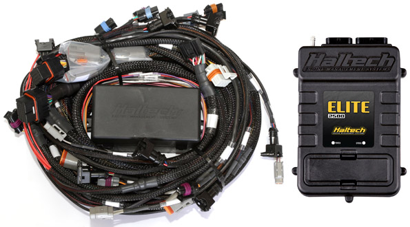

On the ECU side the Terminated Engine Harness includes Haltech ECU connectors and an optional CAN Wideband connector.

On the engine side you’ll find an array of fully terminated engine connectors including a pre-wired plug for the OEM 7 Pin coil harness connector and a group of unterminated in-cabin wires. All the wires are clearly labelled eliminating any guesswork.

The harness also includes a fuse box with five fuses and five relays.

We have also included a 2″ gromit to protect the harness as it passes through the firewall.

With a Haltech Terminated Harness your LS can be wired up and running in a few hours and, when installed in conjunction with a Haltech Elite 2500 ECU, it opens the door to virtually limitless performance modification and tuning options for your vehicle. Haltech Terminated Harnesses are available for most popular LS variants of engines.
![]()
![]()
Tech Tip: How to crimp like a pro
Crimping – for many it’s a daunting task that is best avoided or left to highly specialised experts. The truth is crimping needn’t be hard or difficult. With the right tools and a bit of knowledge you can quickly become a crimping expert yourself!

Having the right tools certainly makes crimping easier. You can purchase the Dual Crimper Set like the one Scott uses in the video directly from our online store:
![]()

