Category: Tech
Firmware Update Nexus V1.24.1 and Elite V3.10.1 – October 2023

New firmware versions are available for the Elite and Nexus range of ECUs, for all the juicy details please check out the full release notes available within the NSP software, however, we wanted to share a few of the highlights with you.
The big one is the new MAP prediction and Fuel film model under Fuel Tuning. This is a new alternative to the Transient Throttle function and is used to smooth out any hesitation or “flat spots” when rolling on the throttle. Our beta testers have been raving about this new function, some even said the words, “It’s the best update ever, it’s like a new ECU!” – So be sure to check that out.
Another favourite new feature is the addition of “Exhaust Cutout”, “Nitrous Bottle Opener” and “Generic Open Loop Motor Controller” functions. These allow a DC motor to easily open or close a valve without position feedback, for use in such situations as – you guessed it, a Varex-style exhaust cutout, or operating a Nitrous Bottle Valve.
There have also been improvements to Cruise Control behaviour, Line Pressure Control and Per-cylinder Knock Control (That one is NEXUS only, sorry Elite guys).
We’ve also added trigger patterns for:
- Mini – Classic EFI – Rover Mode1 Flywheel Crank
- Rover – K Non-VVC Late with Home
And Vehicle CAN options for:
- Subaru WRX MY17
- Nissan Navara D40 2012
You’ll need to be running NSP version 1.34.0 or newer to upgrade your Haltech units to this new firmware, so make sure you’re up to date there first.
What’s So Special about SR20DET
If you’re a JDM fan you’ll probably agree that the 1990s was the golden age for Japanese performance engines. We got the 2JZ, the RB, the 4G63 as well as the Honda K-series. All over-engineered, and all capable of producing power well above their factory spec. But there’s another engine that we haven’t covered yet and one that definitely belongs in that group – Nissan’s SR20.
The basics
The SR series engines were designed as a replacement for the aging CA series and came in a variety of models and capacities, but today we’ll focus on the SR20DET – which is the performance model of the group and the successor of the CA18DET. So what exactly is the SR20DET? Well, like all Nissan engines, it’s right there in the name. SR is the engine series. 20 refers to the engine size or capacity of 2.0 liters, D stands for Dual overhead camshaft, E stands for Electronic Fuel Injection, and everyone’s favorite, the T, stands for Turbo.


Initially, the SR20 appeared in the engine bays of Bluebirds and Pulsars, including the famous Pulsar GTI-R and it wasn’t until 1991 that the SR20 finally arrived in the longitudinal placement we all know and love, in the Nissan S13. The SR20 turbo stayed with Nissan’s S-chassis until the end of its production in 2002. Despite being in production for over 13 years in practically every configuration imaginable and powering 18 different Nissan/Infiniti platforms, the only variants that made it to America were the naturally aspired SR20DE found in Sentras, Pulsars and Infiniti G20s.
Most JDM enthusiasts will tell you that the SR20DET is a longitudinally mounted engine (that is, north south oriented). However, the turbo engine was actually first introduced in a transverse engine configuration in the engine bay of the Nissan Bluebird 2000SSS.

Horses for courses
Horsepower junkies will often argue against the SR20DET engine, since it’s not based on an iron block or that its output can’t compete with that of the inline six-cylinder RB or JZ engines. However, there are compelling reasons to go down the SR route, depending on your application.

The SR’s aluminum block in a Front-engine, Rear-drive setup, helps to maintain the excellent weight balance that the S-Chassis is known for. That, in turn, contributes to the car’s neutral handling. The RB and JZ engines weigh considerably more, which puts more ballast toward the front, which is fine for a drag car, but if you want to go round corners in a drift, rally or circuit-style car – that’s less than ideal.


Which one to get?
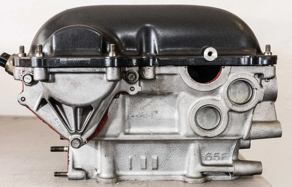
Early S13 SR20s were commonly identified by their valve cover. The “Red Top” and “Black Top” (these were sometimes referred to as “Flat Top” as well) engines came with a “High Port” cylinder head with non-variable timing camshafts. The engine made use of 370cc fuel injectors and a Garrett T25G taking care of forced induction. All this translated to 205hp and 203lb-ft of torque, pretty healthy numbers for a compact sports coupe.

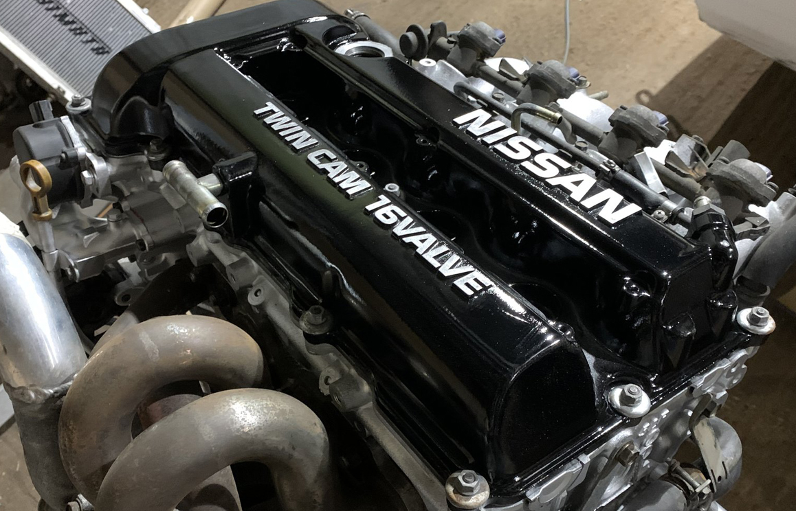
S14 Silvias came with Nissan’s newly updated SR20DET with Variable Timing Control (VTC). This engine, characterized by its unusually shaped valve cover, earned it the nicknames “Notch Top” and “Slant Top.” The new cylinder head, known as the “Low Port,” features a redesigned intake manifold feeding slightly smaller ports for increased intake velocity. This engine received a larger, Garrett T28 turbocharger which, combined with the VTC and new cylinder head design offered improved response while delivering greater peak power of around 220hp.

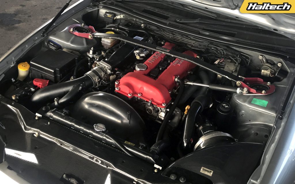
In 1999, Nissan unveiled the final S-chassis to be powered by an SR20DET engine, the S15 Silvia. The SR20DET that powered the S15 Spec R continued to benefit from the VTC cylinder head and came equipped with a Garrett GT28R ball-bearing turbocharger and bigger, 480cc injectors.
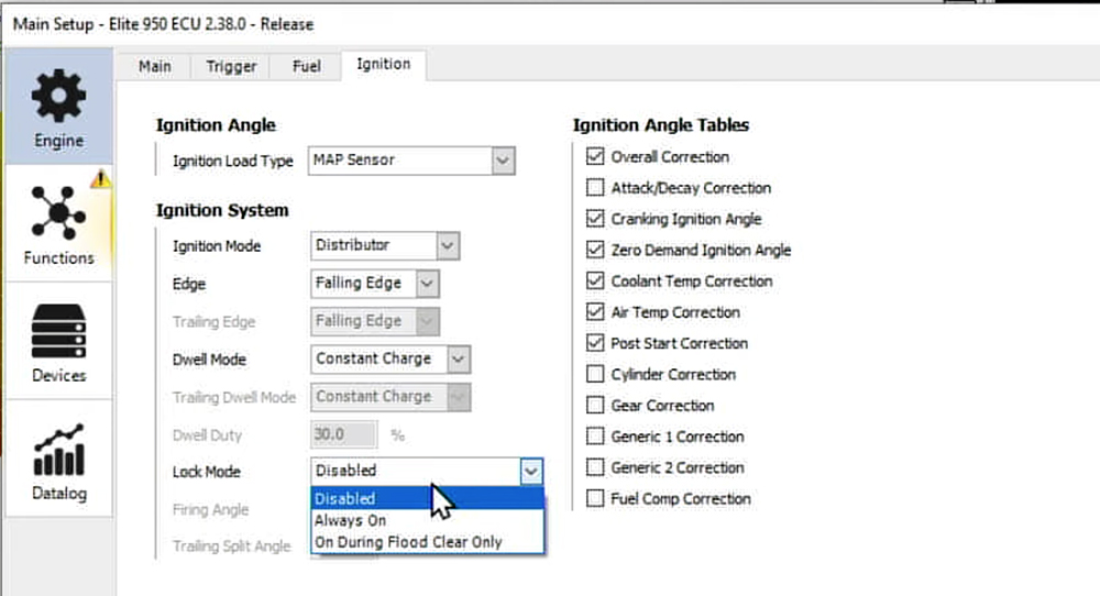
For this engine, Nissan eliminated the “dumb” coils with the external igniter in favor of “smart” coils with built-in igniters. An improved engine management system regulates the fuel delivery and ignition timing to produce 247hp.

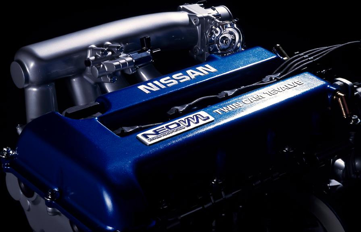
So which one of these is best? While they’re all fairly solid options and all can make decent power, our pick would be the version found in the S15 Silvia, or, if you can find one – the version with the Neo VVL head with variable timing and lift control (though this one never came stock in the Silvia platform).
Things to watch out for
Just like any second-hand engine, there are things that you’ll need to look out for when buying. This is especially relevant with engines that came from Japanese performance cars and have more than likely had a pretty hard life.
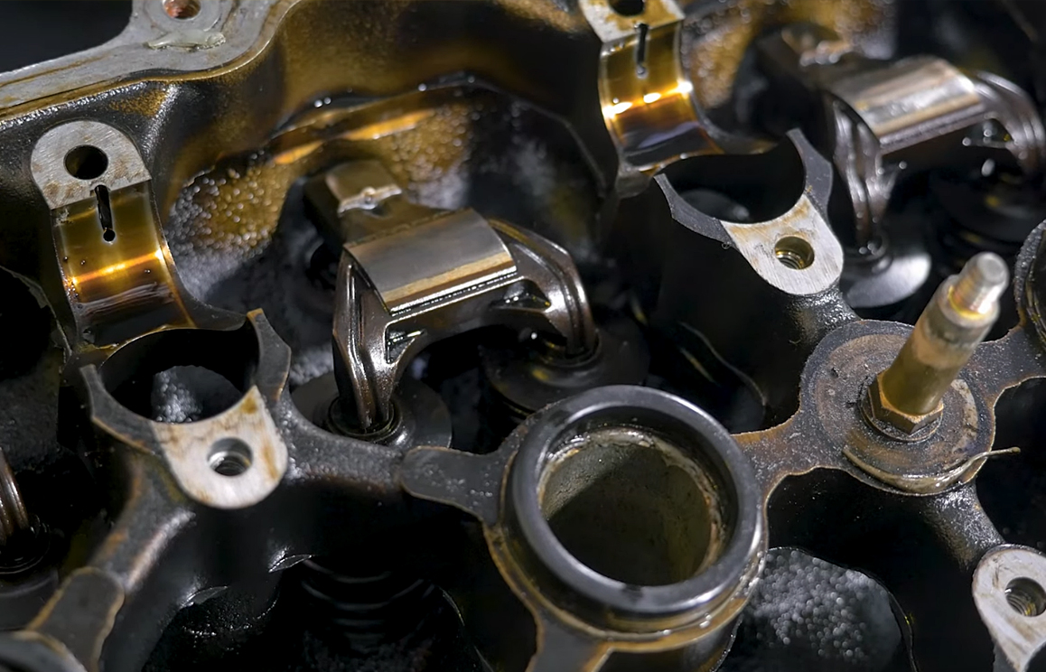
SRs can suffer from oiling issues. The oil pan is relatively small and the oil pickup is located only a few millimetres from the bottom of the pan. So, if the pan takes a hit from a rock, speedbump, or particularly aggressive bottom out while flying down the touge, it can in turn hit the pickup which will crack at the top and lose suction. At that point the engine won’t be getting the oil it needs to survive.
With that in mind, it’s the high-wear areas that you’ll want to pay attention to, due to the age of these engines now. Hard driving conditions and age are certainly wearing rings and cylinder bores, while low oil pressure can lead to spun bearings. And, as many SR owners told us, these engines frequently throw rocker arms, as a side effect of valve float.
Like any engine that is starting to get a bit long in the tooth, it also wouldn’t hurt to take a look at the injectors and ignition system fitted if you are planning on using any of the original stuff.
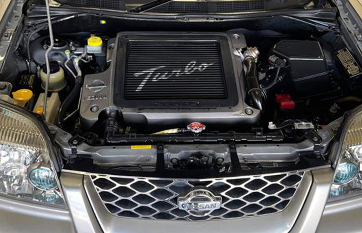
Swapping your standard cylinder head for the VVL Neo or VE type is one of the most popular and most effective mods for the SR20. This head can be found in the JDM spec Primeras, Bluebirds, and the Nissan X-Trail. The VVL head offers improved airflow, higher compression, and improved coolant passages, and in our opinion is the best base to start with in a performance SR20 package.

Popular Mods and Tuning
The bolt-on friendly SR20DET welcomes most modifications and will reward you with increased power and if done correctly, reliability. Once you’ve made the usual intake, downpipe, and exhaust upgrades, investing in an aftermarket engine management solution is going to be your next step – because you’re going to need it to get the best performance out of further modifications like intake manifolds front-mount intercoolers, upgraded injectors, fuel pumps, ignition systems, exhaust manifolds, and of course the ever popular – upgraded turbocharger and big boost!
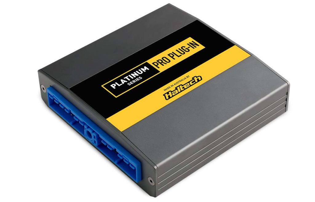
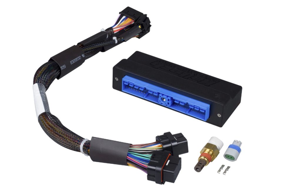
Haltech offers Plug’n’Play solutions for all S-chassis applications from S13 to S15. The affordable Platinum Series Plug-in ECUs connect directly to the factory harness, while the Elite ECUs connect via an adaptor box and harness. In both cases the installation is really simple and once plugged in, all you need to do to get the engine running is load the base map. You’re now ready to tune.
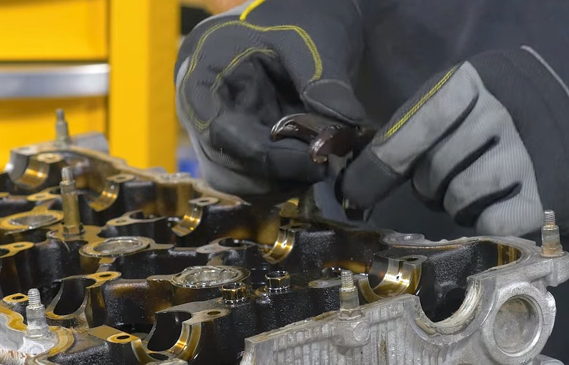
SRs are well known for throwing rocker arms, so if you’re taking the valve cover off to upgrade the camshafts, it’s a good idea to add rocker arm stoppers to keep them in place. If you’re hardcore, ditch the hydraulic valve lifters in favor of solid lifters. Since solid lifters can’t “pump up”, they reduce the chances of the rocker arms being flung from their positions. The only caveat here is that solid lifters are quite fiddly when it comes to dialing in the valve lash. Even so, many argue that the effort is worthwhile since they probably won’t need to be adjusted for quite some time.
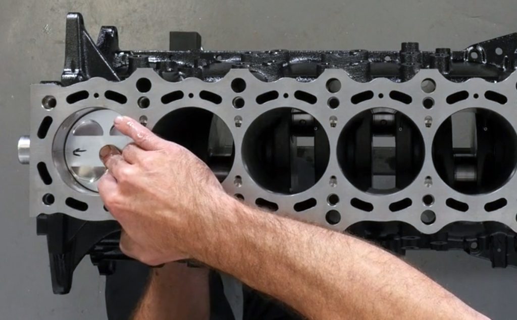
When you’re ready to step up to the next level, it’s time for engine internals. The alloy cylinder liners of the SR20 can only be over-bored 0.5mm or 20,000ths of an inch twice (86.5mm and 87mm) before the liner walls are too thin and you are forced to re-sleeve the block.
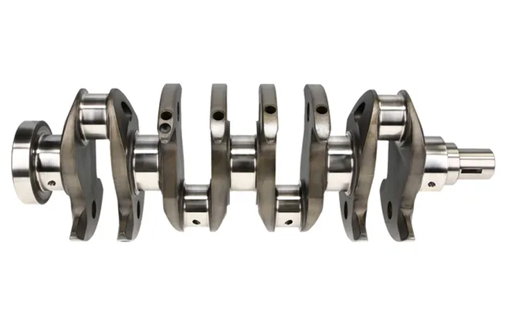
Fortunately, there are a few choices available when it comes to re-sleeving a block, and aftermarket ductile iron cylinder sleeves mean you’re open to using much larger pistons. It’s also a good idea to upgrade connecting rods at this point, considering the engine is already stripped down. There is no shortage of aftermarket internal engine parts for the SR20, including stroker kits or even billet cranks.

As always, improving the airflow in and out of the cylinders is going to improve performance. You can install higher lift and longer duration camshafts, along with larger valves and port work. But remember, bigger isn’t always better. Head porting, valvetrain, and camshaft selection go together with turbo sizing to achieve the desired peak output and torque curve.
Going big with high peak power output is great if you’re drag racing, but usually means the down-low torque will suffer – so make sure you are getting the right cylinder headwork for the kind of work the engines going to be doing.
If you’re thinking about taking your SR20 apart and upgrading the internals we highly recommend doing an interactive engine building course with High Performance Academy. They actually have one specifically for the SR20. See links at the end of this article.
But wait, there’s more…
If you’re a big fan of the SR20 but you’re not too keen on rebuilding an old engine, we might have some really good news for you. Rumour has it that after over two years of negotiations, Nissan sold the tooling and the design files for the SR20 to a Japanese firm called Mercury Enterprises. The company plans to build crate engines and make them available to the public. Now for the bad news; the initial quantities will be very small – we’re talking a maximum of four per month so the wait for your brand-new SR20 might be a few years!
Resources
Haltech’s Range of S-chassis and SR20DET compatible ECUs
High Performance Academy SR20DET Engine Building Course
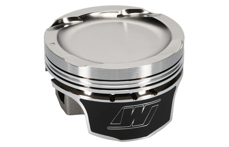
Wiseco SR20DET Performance Pistons and Rods
K1 Technologies SR20DET Billet Crankshafts
NTK Wideband Sensor Firmware Update – May 2023

What is this?
Nexus Firmware Update V1.22 and Elite Firmware V3.08 include an important update to the functionality of NTK Wideband sensors. This update will require NTK users to perform a free air calibration, followed by an engine re-tune.
Why are you doing this?
Adding the free air calibration for NTK sensors improves the accuracy of these sensors, and allows the Haltech software to better compensate for variations in individual sensors, due to manufacturing tolerances and/or age and wear of the sensors.
Who does it affect?
All Nexus users and Elite users with NTK wideband sensors.

When will I have to perform the free air calibration?
Initially, you will be required to perform the calibration as soon as the firmware update is complete. You may also want to periodically perform the free air calibration to check ongoing sensor health.
Can I skip this calibration?
Yes, however, wideband/lambda control will be disabled until the free air calibration has been completed.
Do I need to remove the sensor from my exhaust for the calibration?
Yes, this is a free air calibration and it is best practice to remove the sensor from the exhaust to perform the calibration.
Will I need to retune the engine after performing the calibration?
Yes. During the firmware update, the indicated air-fuel ratio will likely change (even though the actual air-fuel ratio should not). This may require changes to the target lambda table and the fuel map to compensate. Therefore vehicles using closed-loop O2 control must be retuned, in all other cases, we strongly recommend a dyno checkup after upgrading the firmware and performing the initial sensor calibration. This should not be necessary after subsequent calibrations.
I did the calibration, but the software still says my sensor is uncalibrated – what gives?
It is likely that your NTK sensor has worn beyond its usable range and needs replacing. The software was previously unable to detect this.
After the initial calibration, will the sensor require ongoing recalibration?
Yes, in rich methanol mixtures, best practice would be to run the free air calibration before the engine sees heavy load. Eg: Dyno power runs, full noise drag passes.
I have a Bosch wideband sensor, do I need to do the calibration?
No. Only NTK sensors are affected

Buying a second-hand ECU
Are you thinking of buying a second-hand ECU? You can get a great deal on a used Haltech ECU on popular sites like eBay, Facebook Marketplace, Gumtree, Craigslist or Trademe. But just like with any other second-hand product, there are some things you need to keep an eye out for.
Visual Inspection
The first thing to do is a visual inspection – Here’s what to look out for:
Check the pins inside the connector to ensure that none have been melted from a fire or because of a serious wiring problem.
Check the screws that hold the ECU cover to the backing plate – If they’re missing or look like they’ve been tampered with, it is possible someone has tried to pull the ECU apart to look inside, and there is almost never a good reason to do that. If they’re rusty, that could be an indicator that the unit is water damaged, and best left alone. Water-damaged electronics aren’t a good buy.
Have a sniff! Yes, really. Burned electronics have a distinct smell, if you can smell anything funny, walk away.

Serial Number
Do check for a serial number. It should be on a silver sticker stuck somewhere on the unit. Firstly, make sure that the sticker doesn’t say “Display” – If you’ve got one of those, it is a dummy unit someone has stolen from one of our event display stands.
Once you have a serial number, you’re welcome to email that to us at Haltech. We can give you the production date of the ECU, and tell you whether anyone has ever reported the unit stolen to us. If you happen to come across an ECU without a serial number sticker, don’t panic. Once connected to Haltech software, we can see the unit’s serial number, and give you that information.


Firmware, Software and Accessory Compatibility
If you’re looking at a Platinum series ECU, you’ll need to run Haltech “ECU Manager” software on your computer. While stable and quite capable, ECU Manager is getting on a bit now and is no longer getting any updates. Don’t let that stop you from looking at a Platinum ECU, though. They’re still a very capable unit, especially for the second-hand price.
All Elite and Nexus units now run on the current NSP (Nexus Software Programmer) and can be updated to the latest version no matter when they were manufactured.
All Nexus, Elite and even Platinum Sport ECUs have a CAN port and can make use of the bulk of Haltech’s current range of CAN devices, such as a Wideband Controller, or iC-7 Dash. CAN Keypads will not run on the Platinum range, however. Platinum and Elite ECUs share the same connectors, but be careful if you’re upgrading from a Platinum to an Elite ECU because the pinouts are slightly different. If in doubt, you can always contact our support team to help you with that.

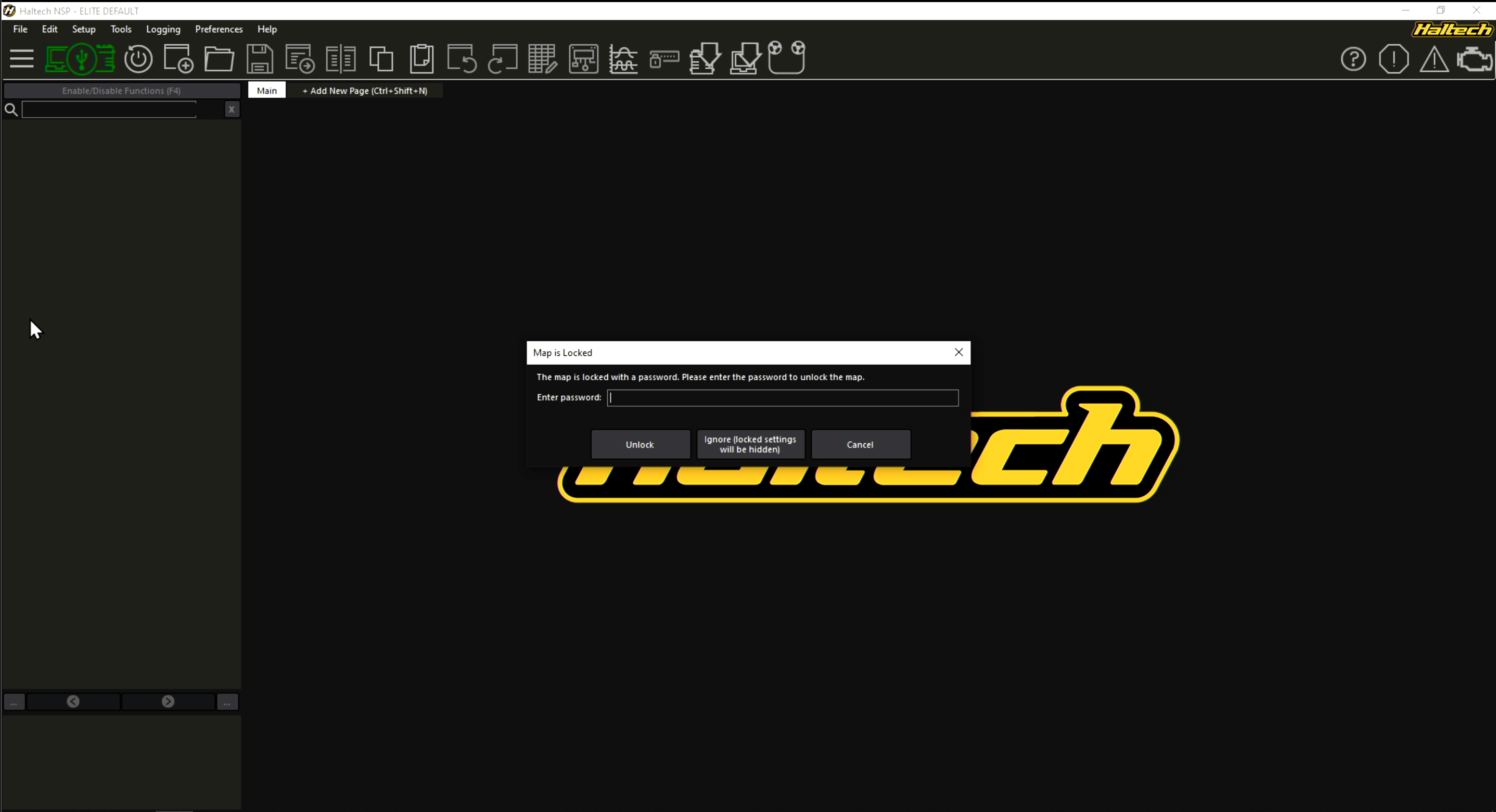
Password Protection
Sometimes second-hand ECUs will come to you with password protection enabled. Again, don’t panic! You’re not locked out of your ECU. What you are locked out of is the “map” that was created by (or for) the previous owner. All maps/tunes remain the tuner’s intellectual property, so they’re entirely within their rights to put a password on them. While you cannot reset the password to access those maps, you can run a factory reset and set the ECU back to factory default. This is fine because if you’re buying a second-hand ECU, you’re not likely to use the old map anyway!
Haltech ECU Health Check and Repairs
If you happen to find a great deal on a second-hand Haltech ECU, only to be disappointed when it arrives and you find it is damaged, or not working, don’t despair. Haltech has an amazing after-sales and repair service, and in many cases, a Platinum, Elite, or Nexus ECU can be repaired. You can find the repair return instructions on our website.
Alternatively, if the ECU seems fine, but you want to be 100% sure it’s fully functional before you install it, you can send it to us and, for a small fee, we can test it and provide you with a condition report, just for your own peace of mind. While we’re at it we can also update the firmware and software to the latest version available.
Price Check
And finally, before you pull the trigger on purchasing a second-hand ECU, make sure you check our website and see what you’d pay for a brand new unit – It may not be a lot more than the second-hand unit you’re looking at!
Installing a stand-alone iC-7 dash
Whether it’s a mechanically injected monster, or a reliable, carbureted cruiser, the Haltech iC-7 standalone “Classic” kit is a great option for modernizing your old dash cluster. Today’s patient is this 1986 Jeep Wagoneer and we are about to breathe new life into this classic ride by upgrading it to the Haltech iC-7 colour display.
With its digital fuel gauge, customisable screen layouts and plug and play compatibility with other Haltech CAN devices, this upgrade really was a no-brainer. Below is a quick, step-by-step guide on how we got it done.


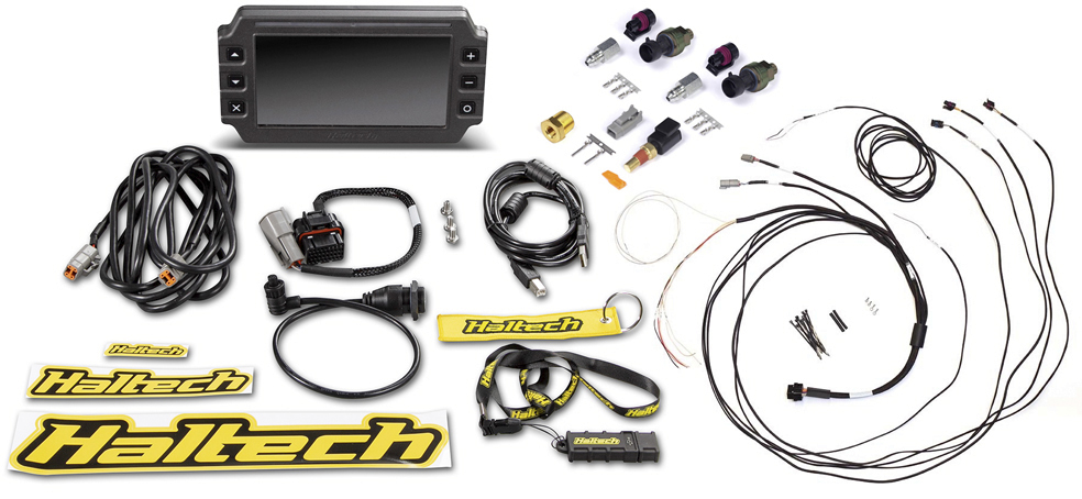
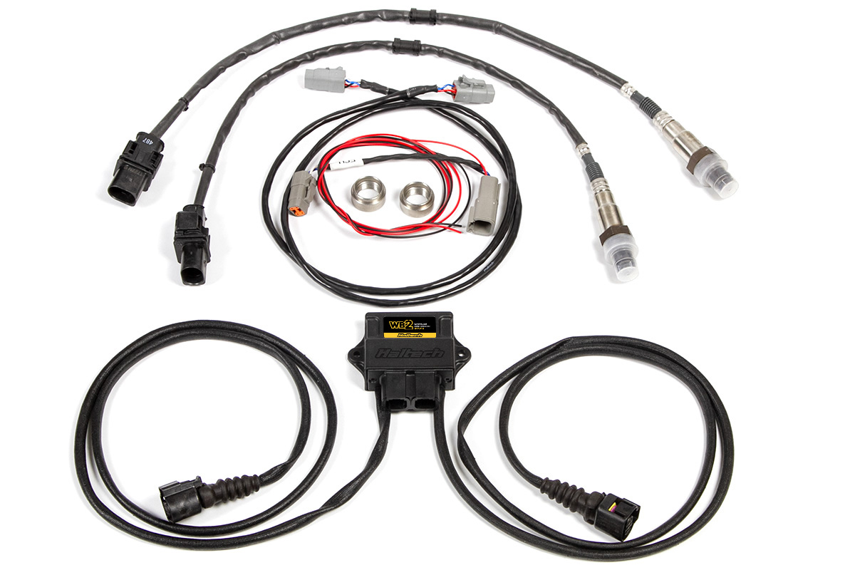
What you get with the Standalone iC-7 Kit
Apart from the 7″ digital display dash, the iC-7 Standalone “Classic” Kit includes a sensor pack, 34 Pin main connector harness, DTM-4 to DTM-4 CAN extension cable, USB to M5 right angle cable and a semi-terminated iC-7 harness.
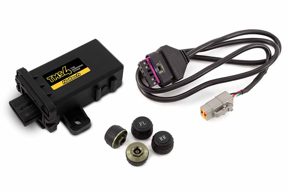
The standalone iC-7 harness includes connections for three sensors of your choice, as well as a fuel level sender. It also has a connection for a vehicle speed sensor and a CAN connection port. This device is plug-and-play with our CAN-based tire pressure monitoring system TMS-4 and can also connect to our WB1/WB2 Wideband modules, or the TCA EGT modules. The sensor pack includes a coolant temp sensor 1/8 NPT, a brass adaptor 1/8″NPTF to 3/8″NPT and two 150PSI “TI” fuel/oil/wastegate pressure sensors.
Optional Extras
This Grand Wagoneer came with a carbureted AMC 360 V8 and a Chrysler automatic transmission. It’s mainly used for summer transportation and some light off-roading on the weekend. For this install, we are going to opt for a coolant temperature sensor, a fuel pressure sensor and an oil pressure sensor. We will also upgrade to the optional GPS Speed module as well as the CAN-based TMS-4 and WB2 systems.
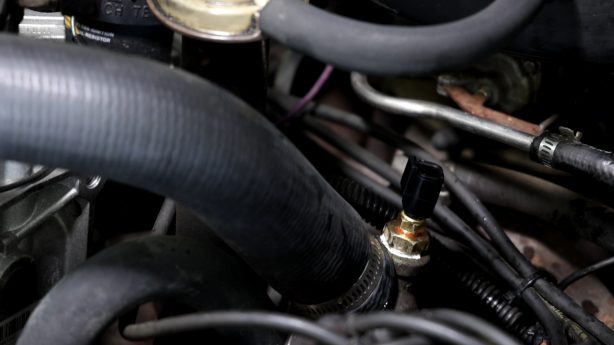
Sensor Installation
We need to scout out our sensor locations, luckily a quick web search found us the factory locations for most of these. The oil pressure sensor is a 0-150 psi transducer with a 1/8″ NPT connection; this will easily install the factory location on the passenger side of the engine block. A quick cleaning, a dab of paste, and we are ready to tighten and connect it to our standalone harness.
Our coolant temperature sensor is actually going on the water neck, there is a convenient 3/8″ NPT port. Using the included 3/8″ NPT to 1/8″ NPT reducer allows us to screw in the new sender. Finally, the fuel pressure sensor will go into our factory soft line connection just before the carburetor. A brass inline gauge port tee provides the 1/8″ NPT port required to install the sensor.
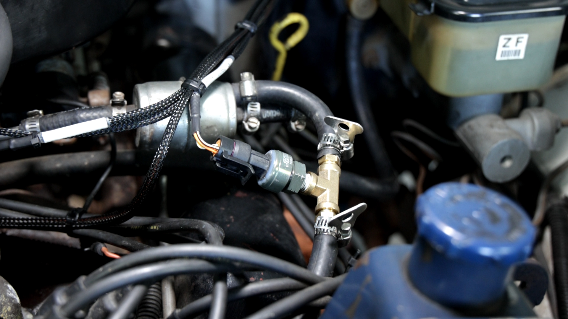
NOTE: This sensor is rated up to 150 psi and although this application is carbureted (5-7 psi), it will also work with mechanical systems that see much higher pressure readings.
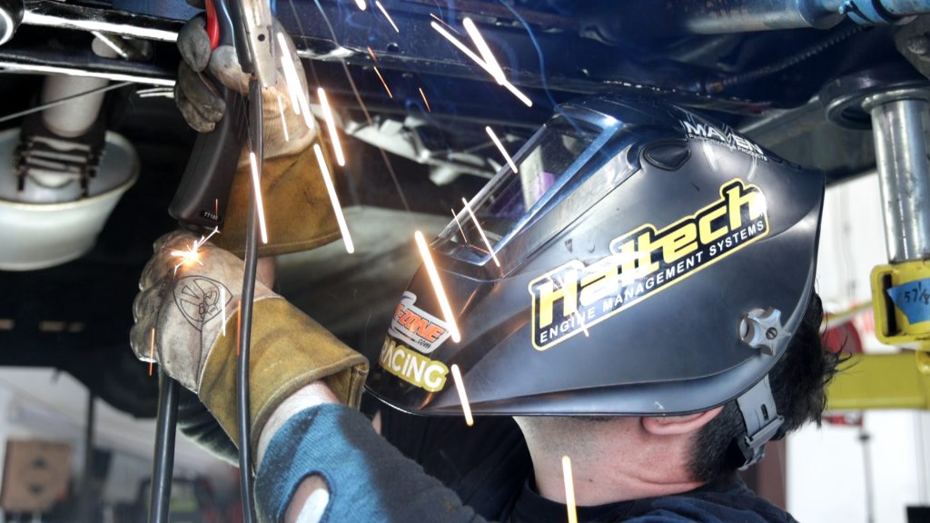
O2 Wideband Sensor
Now it’s time to get this thing in the air and get a WB2 wideband oxygen sensor module installed in the factory dual exhaust. While we are limited on tuning with the factory 2-BBL carburetor, the owner plans to use an aftermarket intake and 4-BBL carburetor in the future.
These sensors will be an awesome tool for dialing in performance after those upgrades. A good rule of thumb is to place the bung/sensor approximately 6-10″ AFTER the merge on one bank. For this application, that means after the manifold collector for each side.
It’s worth mentioning that the “FUEL LEVEL” input includes a pre-terminated connector and a flying lead wire giving us the ability to create a harness for the sending unit that can easily be disconnected if we need to drop/service the fuel tank. The ICC software is pre-programmed with a ton of popular ohm ranges, but a custom calibration table is included if needed.
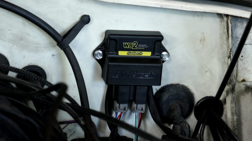
TMS-4 and WB2 Controller
With the Jeep back on all fours, it’s time to install the tire pressure monitors. Haltech offers both internal or external sensors, but for ease of installation and quick interchangeability, we opted for external units. No calibration is needed once the TMS-4 module is connected to our display using the included CAN cable. Now it’s time to mount our WB2 and TMS-4 modules on the firewall, this gives us easy access to connect our CAN cables and connections for the dual wideband oxygen sensors.
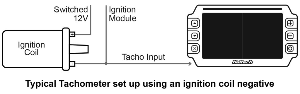
The only other thing to do under the hood is to wire in our engine speed input (Tach), luckily our factory ignition coil had a provision for a tach wire even though the stock instrument cluster didn’t show RPM. A quick spade connection on the standalone harness and we were finished with the engine bay.
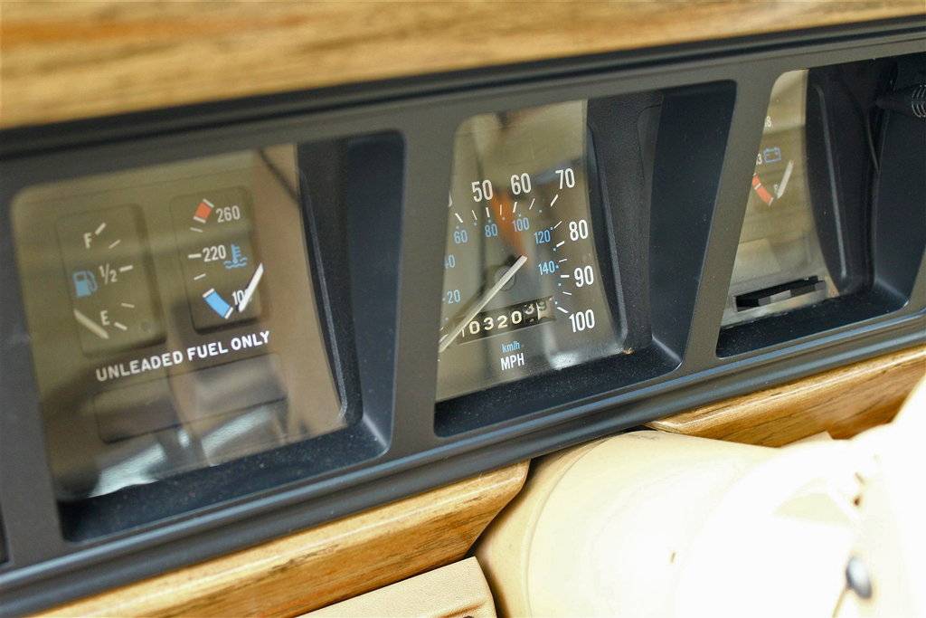
In-cabin wiring
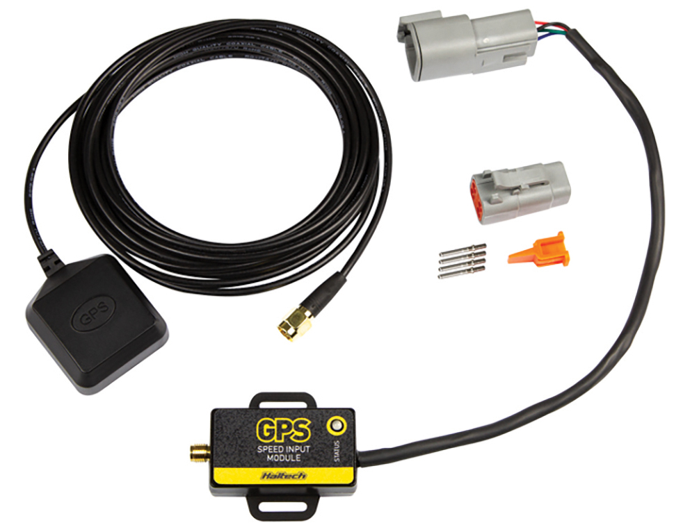
With our engine bay wiring and sensor installations complete, it was time to tackle removing the factory cluster and modifying the harness to adapt to our iC-7 display. Our Wagoneer used a mechanical speedometer cable, but after years of reliable service, it was time to upgrade to the GPS speed input module.
This plug-and-play device mounts an antenna with a single cable connection and calibrates with a simple check box in the Haltech ICC software. Not only will it register GPS speed (in mph or kph), it can also be used for odometer and trip meter readings.

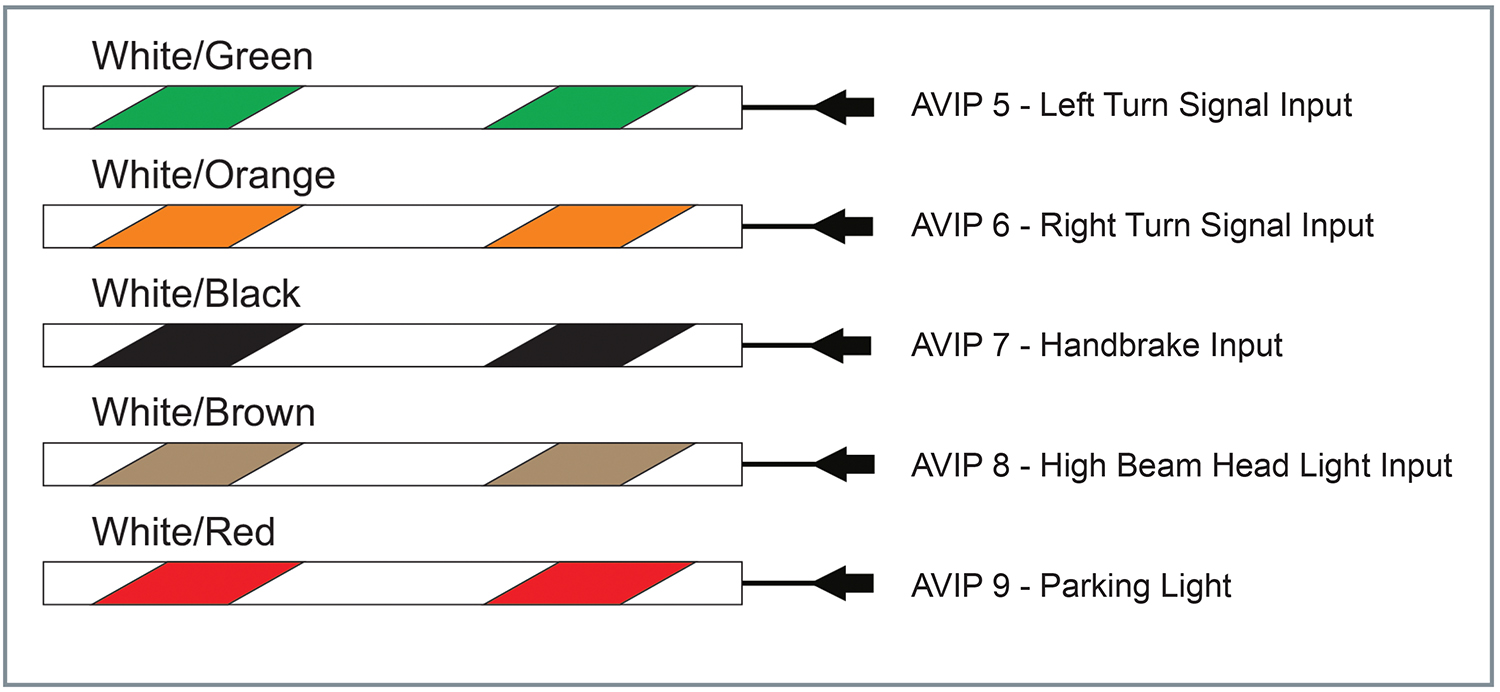
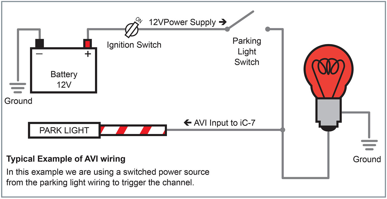
The factory cluster wiring gave us a nice selection to tap into for our accessories, including turn signals, high/low beam, and our fuel sender wire. We should note that with the exception of the fuel sender and the handbrake connection, all other inputs will be positive trigger-based. Reference the diagram below for an example of how to wire up your parking lights.
While a swarm of butt connectors could do the job, we felt it was better to wire in an 8-pin Deutch connector. This not only cleans up our dash wiring but also provides a simple disconnect in the event we need to remove our dash in the future. While we were at it, we ran the switched +12v and ground connections to our fuse block wrapping up all of our wiring.
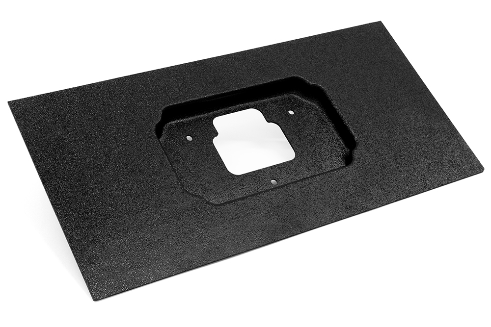
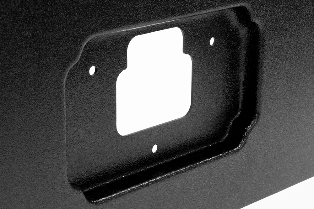
Final Details
With the dash wiring completed, the only thing left to do was mount our 7-inch display. Using a universal moulded panel (sold separately), we created a bezel that attached to the rear of the iC-7 and allowed the cables to pass through. After making a few measurements and trimming, the bezel could use the factory mounting points and fit snugly into the Grand Wagoneer’s dash. And we’re done!
Software setup
The final step was to connect to our iC-7 display through the included USB communication cable and load the new standalone firmware through ICC. If you’re unfamiliar with our software package, read on to learn more about configuring sensors as well as other inputs!

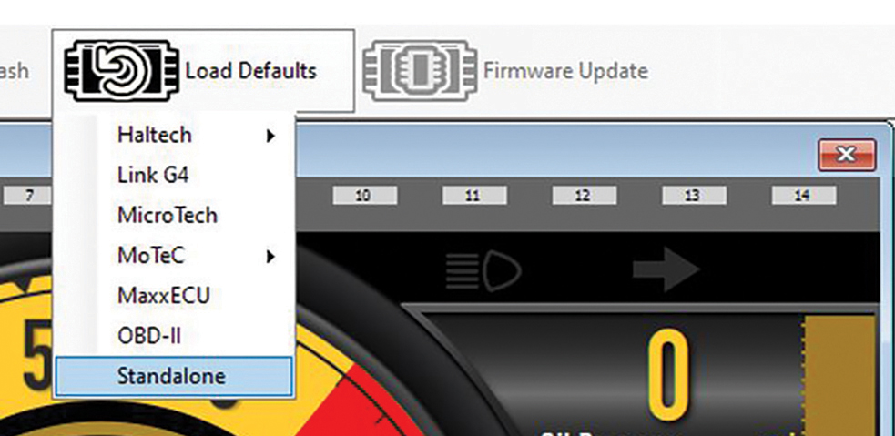
Loading iC-7’s Standalone Default
From the main screen click on the “Load Defaults” menu and select “Standalone”.
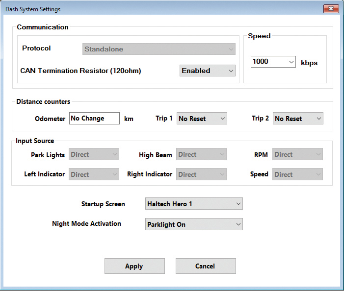
All the iC-7 inputs are now automatically set to “Direct” input mode.
Speedometer Input
The speed sensor provides a signal that, when received by the iC-7 can be used to display vehicle speed and/or set up speed-based alarms. The Haltech iC-7 harness will connect directly to a Haltech GPS Speed Input Module (HT-011310) without any additional calibration or configuration required.
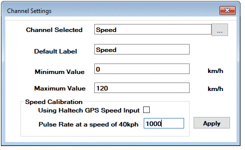
You can also connect your iC-7 to an existing OEM vehicle speed sensor. In the Channel Settings window untick the “Using Haltech GPS Speed Input” box. If you already know your sensor’s Pulse Rate (PPM), enter it and click “Apply”.
If you don’t know your sensor’s PPM calculate it using the following steps:
1. Ensure your speed sensor and iC-7 dash have a common power and ground supply.
2. Connect the sensor signal wire to “SPEED IN” (Pin 33).
3. Display the Speed Pulse Rate channel on an available gauge.
4. Drive the vehicle at 40KPH (25MPH) and note the Speed Pulse Rate value. You will need an external device (such as a GPS Speed smartphone app) to reference vehicle speed.
5. Enter the Speed Pulse Rate value in the relevant box and click “Apply” and you’re all set!
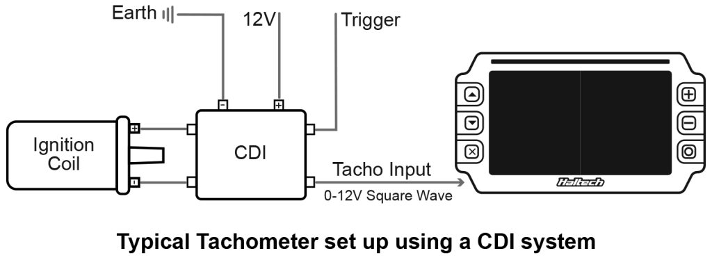
Tachometer Input
The “TACHO IN” is used to supply the display with the engine’s RPM signal. This signal can be provided by multiple ignition types. The “TACHO IN” input is an unterminated flying lead type that allows for easy integration into many different types of OEM and custom-made wiring harnesses.
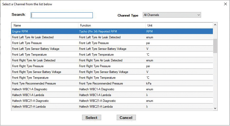
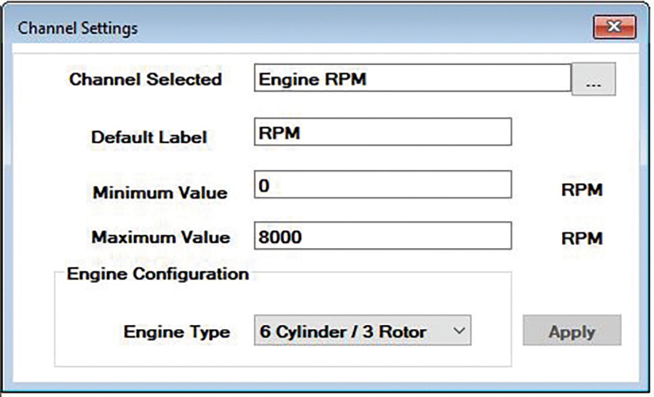
Connect this input to your current tachometer input wire. This wire can originate from a factory ECU, an ignition coil, or your engine wiring harness. To configure the RPM (TACHO IN) channel in the ICC software, select the tachometer on the main dash layout page. In the “Channel Settings” dialog box set your minimum and maximum RPM values (eg. 0-8000). Choose your engine configuration from the “Engine Type” drop-down menu and hit “Apply”.
Analogue Voltage Inputs (AVIP)
The Analogue Voltage Inputs on Haltech’s iC-7 can accept variable voltage levels from 0V to 5V.
The pre-calibrated inputs include air and coolant temperature, oil and fuel pressure, and fuel levels (volume) inputs. If your sensor is not listed in the “Sensors Connected” drop-down menu of the “Channel Settings”, you can use the “Custom” option and enter the calibration values manually.
Oil Pressure (AVIP 1)
The connector labeled “OIL PRESS” attaches directly to the Haltech oil pressure sensor. This connection is pre-terminated with a 3 pin Delphi connector.
Fuel Pressure (AVIP 2)
The connector labeled “FUEL PRESS” attaches directly to a Haltech fuel pressure sensor. This connection is pre-terminated with a 3 pin Delphi connector.
Coolant Temperature (AVIP 3)
The connector labeled “CTS” attaches directly to a Haltech engine coolant temperature sensor. This connection is pre-terminated with a DTM-2 connector.
Fuel Level (AVIP 4)
The flying lead connection labeled “FUEL LVL AVIP 4” is used to connect your existing fuel level sender to the iC-7 Display Dash. The harness also features a DTM-2 in-line connection for servicing.
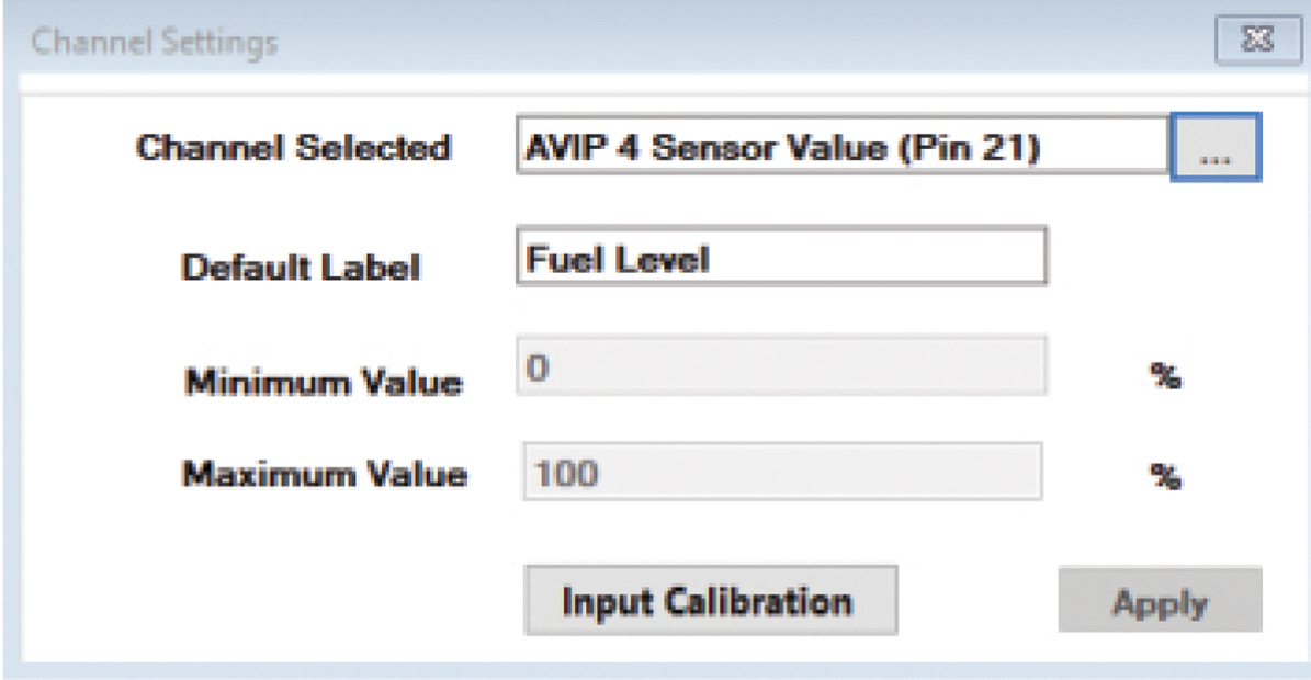
Once connected you can you calibrate your fuel level sender using Haltech’s ICC software.
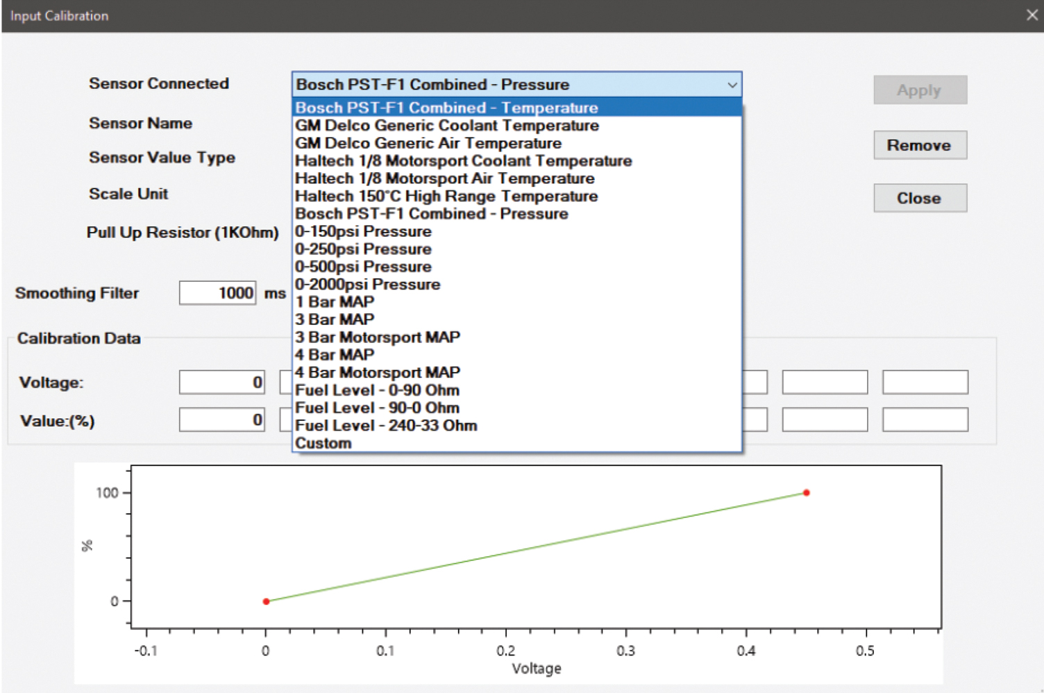
To calibrate your fuel level sender go to “Dash Settings” then “Channel Settings” on the navigation menu. Choose “AVIP 4 Sensor Value”. Select “Input Calibration”.
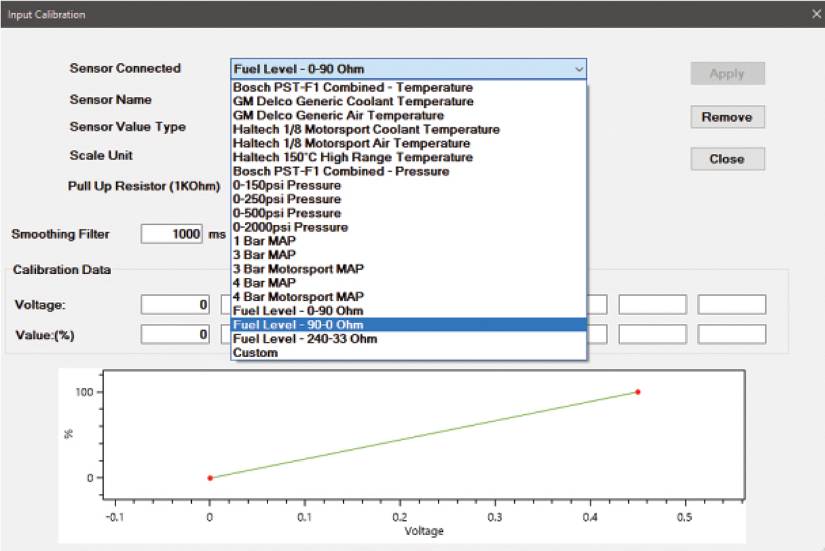
The sensor dialog box will show a list of pre-configured sensors including optional Ohm ranges for common sending units. If you have one of the pre-configured sensors, select it and click “Apply”.
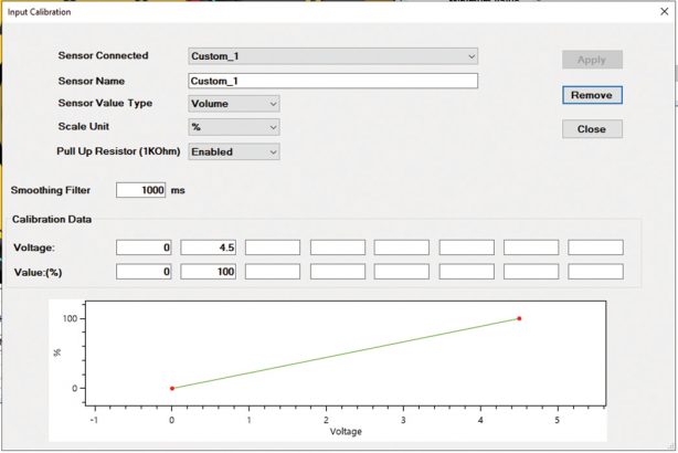
If your sensor type or Ohm range is not listed, you will need to input the “Custom” sensor type. With the fuel sender connected to your iC-7, connect a Voltmeter across your fuel sender gauge posts, and measure the minimum and maximum float height voltages.
Input those voltages to their corresponding value (0-100). For maximum accuracy measure all eight data points. Otherwise, leave them blank and allow the software to interpolate the values.
Oil and Fuel Pressure Configuration
The AVIP1 and AVIP2 channels are already pre-configured for Haltech’s 0-150 PSI pressure sensors. They are labeled “Oil Pressure” and “Fuel Pressure” respectively. Follow the steps below if you need to change the sensor type or the display target of this channel:
1. Choose “Dash Settings” / “Channels” from the navigation menu.
2. Choose “AVIP1 Sensor Value”. You can change its default label “Oil Pressure” if required.
3. Select “Input Calibration”.
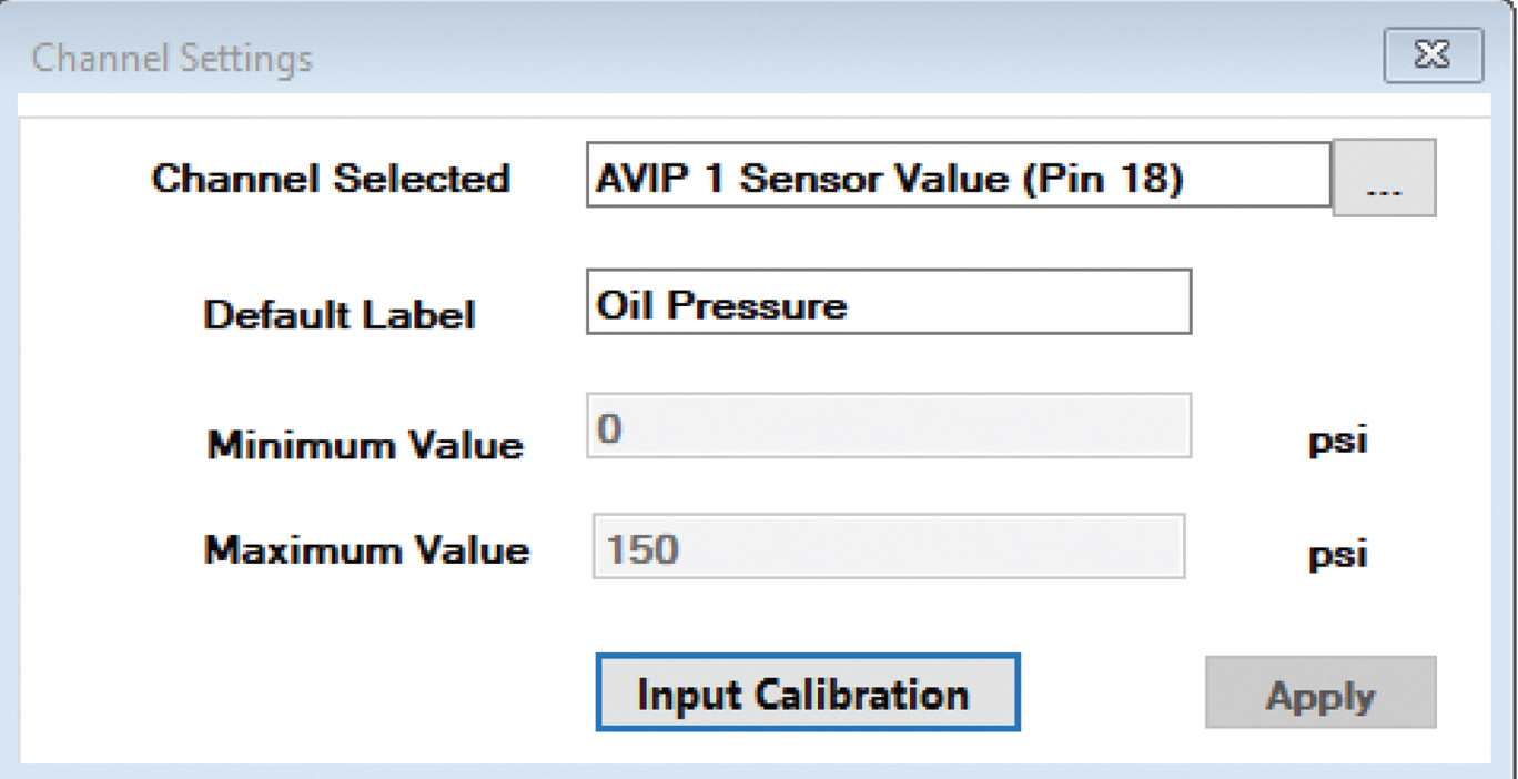
From this dialog menu, you can choose a different sensor type. You can also input a custom sensor type providing you know the voltage range and values for that sensor.
Most pressure transducers have a range of 0-5V, but this may vary and it is important to obtain the correct manufacturer’s sensor data prior to calibration.
Prefer watching to reading?
Well, you’re in luck, because we also have a video version of this article where you can see exactly how this install was done. While you’re there, subscribe to our YouTube channel for more tech tips, software walk-throughs and other car-related content.
Haltech iC-7 “Classic” Stand-Alone Kit
Part Number: HT-067014
Screen: Full colour 7” TFT display
Outside Dimensions: 217 x 122mm (8.5? x 4.8?)
Compatible with: Carbureted and mechanically injected cars.
All current Haltech ECUs via CAN.

What’s in the box:
• Haltech iC-7 Display Dash
• Semi-terminated stand-alone harness (HT-060300)
• iC-7 stand-alone sensor pack (HT-010001):
– 1 x coolant temp sensor 1/8 NPT (HT-010304)
– 1 x brass adaptor 1/8″NPTF to 3/8″NPT (HT-120000)
– 2 x 150PSI “TI” fuel/oil/wastegate pressure sensors (HT-010904)
• 34 Pin main connector harness
• DTM-4 to DTM-4 CAN extension cable
• USB to M5 right angle cable
• USB Cable
• Mounting Screws
• USB flash drive with iC-7 Software
• Quick Start Guide
• Haltech stickers and a fabric keyring tag
See all the iC-7 Mounting Options Available
Crimping vs Soldering
Does soldering really anneal the wire and weaken it? Can a crimp join really be as strong as a chemical bond? Today we dig into the fundamentals of both methods and find out once and for all which is best.
Battlelines drawn
You have probably heard people arguing about the merits of soldering your wiring connections vs crimping. The “solder is best” camp swears that soldering is more reliable because it forms a chemical bond and that soldering is less bulky and thus better. On the other side of the fence, the crimping advocates warn that the heat generated by soldering is annealing the wire and weakening it while bringing up countless examples of a cracked solder joint.
So who is right? Does soldering really anneal the wire and weaken it? Can a crimp join really be as strong as a chemical bond? Let’s dig into the fundamentals of both methods and find out once and for all which is best.
The case for solder
Soldered connections are formed by melting a small amount of alloy into and around the two wires being joined. This requires the use of a soldering iron and of course the solder material itself. As the solder material is melted, it wicks its way up and into the two wires, and when left to cool reforms as a hard interpenetrating connection that mechanically bonds the strands of two wires together. Looking at a nicely formed solder joint on the surface it’s easy to see why many people believe this to be the ultimate in joining techniques.

Its strong, its not bulky and there is excellent electrical conductivity between the two wires being joined. It’s important to note, once the join has been made, it needs to be covered by an insulating material, either heatshrink or worst case a tape join.

The crimping option
Let’s contrast that now with a typical crimp connection. In this method of joining two wires there is no heat required and no chemical bonding happening. A crimp join just uses old fashion compression to hold the join together. For joining two wires together we typically use something like these open barrel crimps, we overlap the wire and crimp down using a correctly sized crimping tool.

A crimped join is also strong join, it doesn’t need to be bulky and also offers excellent electrical conductivity between the two wires being joined. Again, after the join is made, it should be covered by an insulating material.
Good Join vs Bad Join
We need to be clear here; when done poorly – both soldered and crimped connections are a bad! A good solder join is better than a bad crimp, and vice versa a good crimp is better than a bad solder join.

The Twist-and-Tape method
Okay, let’s quickly address this well-known and frequently used technique. The twist and tape method may have its place – it’s just not in your car, and certainly not in engine management wiring.
The Verdict
So what IS the best way to join a couple of wires in an automotive wire harness? In 90% of cases, the crimp is the superior connection method in a wiring harness and that’s the method we recommend for ECU installations.
But why?
The two biggest problems with solder connections in a wiring harness is corrosion and cracking due to mechanical stress or vibration. Both of these issues are generally preventable with adequate strain relief and joint protection such as heatshrink, or better yet, heatshrink with a glue lining. Cracking of solder joins in wiring harnesses is not an uncommon occurrence, especially after many years of service. There are many examples of OEM vehicle manufacturers’ solder joints cracking or corroding causing any number of issues.
Best applications of solder
That’s not to say there is no place for solder joins in an automotive application. Wherever there is a PCB (printed circuit board) involved, we recommend using a solder join. Another instance where a solder is preferred over a crimp is where we don’t have a mating connector for a sensor and we have to make a direct wire connection between a pin and a wire. In that case we would also solder the wire directly to the pin rather than use a pin to pin connection. It’s highly recommended to also backpot the enclosure to prevent any movement of the wires away from the pin.
Is more better?
If crimping is good, and soldering is not as good but still OK – then is soldering a crimp join the best option available, being a combination of both methods? The simple answer to that, even if it’s somewhat counter intuitive, – is no. Adding solder to a crimp join does not improve the crimp. In fact, it’s detrimental because the additional heat that is added to the wire and the solder inevitably wicks up the wire and can actually weaken the wire itself making the join more susceptible to cracking.
Before you start crimping or soldering
First get a quality set of crimping tools, they’ll make the whole process a lot easier. Find a reliable supplier of open barrel crimps in a multitude of sizes for joining one, two or ten wires together. Get some heatshrink, again in a variety of lengths and diameters. We recommend using a quality glue lined heathrink where the space allows. Don’t forget to add the heatshrink to the the join BEFORE you make the join.

And finally – Don’t be afraid to pull out the soldering iron to make those one-off random connections, but only if you have a way of mechanically retaining the entire join.
Current Basics: Volts, Amps and Ohms
In this article we are getting nerdy about electrons. To be more precise, we are discussing why choosing the right wire gauge is important and why an incorrectly sized wire gets hot. We also go through the governing rules that dictate how much current a circuit is going to draw.
The Basics
Before we even get into the volts, amps, and resistance let’s look at some of the basic types of electrical circuits we deal with in an automotive system.
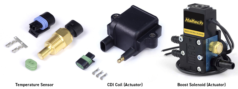
Within the engine bay and from an engine control perspective there are two major types of circuits we deal with. We have sensors, which relay information into the control system, and actuators that are being controlled by a control system – either an ECU or PDM. The actuator is just a technical name for the things in the engine bay that actually do something, like fuel injectors, ignition coils, fans, pumps, solenoids etc. These are the components that the control system is actually turning on and off to make something happen in the physical world.
Today’s discussion of circuits is going to concentrate mainly on the actuators because these are the components that have the highest potential for things to go wrong. For example, if you size the wiring to the fuel pump inadequately, you may end up creating enough heat in the wiring to turn a small electrical problem into a serious fire risk.
Ohm’s Law
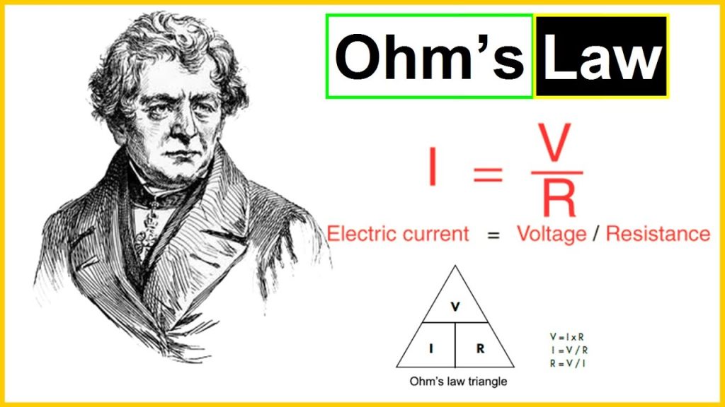
Why is getting the gauge (or thickness) of the wire important for an electrical circuit? The gauge of a wire required is proportional to the amount of current the circuit is drawing and the current being drawn is proportional to the resistance. This is where our old friend Georg Ohm steps in with Ohm’s law.
Ohms law is what we use to relate current, voltage and resistance. And Ohms Law states that:
Voltage = Current x Resistance (or V=IR)
What does that mean for powering up a light globe, a fuel pump, a nitrous solenoid or any other device in our engine bay? Traditionally we’d use a 12V electrical system, or when the engine is running 13.8V. ( That’s what the alternator is regulating the voltage to, in the real world that could be 14.2, 14.4 or even 16V depending on your particular application. If you are not sure, just grab a multimeter, set it to DC Voltage and measure what the voltage is across your battery with the engine running.)
So let’s say we’re using 13.8V, and, according to Ohm’s Law (voltage = current x resistance), all we have to do is measure the resistance of the device we are trying to run to calculate the amount of current that device will draw.
Now that we know the theoretical amount of current the device should draw we can go about sizing up not only the wiring but also ensuring we select an appropriate set of plug and pins to use for each device.
The simplest and most practical way of sizing your wiring appropriately is to use an online wire gauge calculator like this one by wirebarn.com. You simply input the voltage, current and length of wire and the calculator will provide you with a minimum wire gauge for your application.
Why girth is important
Anyone who has used a wire too small for the intended application knows that too thin a wire gets hot, really hot – but why? Why does this heat get generated in a thin wire but not a thicker one?
The answer to that one gets even nerdier and goes all the way down to the sub-atomic level of electrons passing down from one molecule of copper to the next molecule of copper in length a wire.
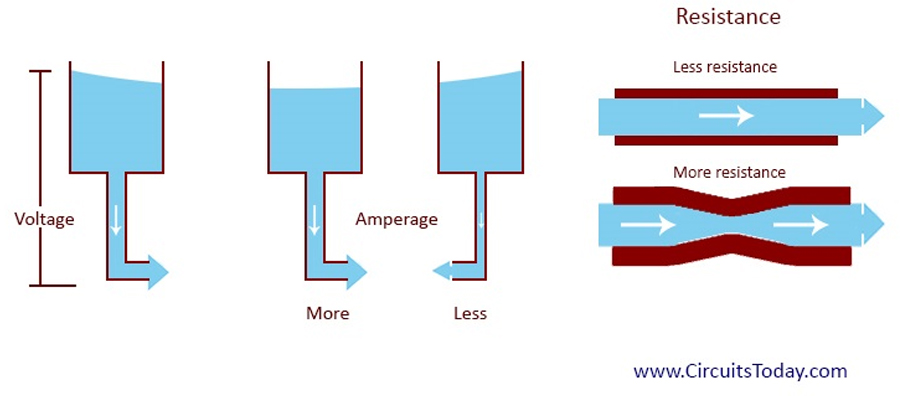
Amps (or current flow), is a measure of the actual number of electrons that are being moved through your circuit. Imagine having to move the same number of electrons through a very thin wire, as opposed to a very thick wire. The best way to illustrate it is with a water hose analogy. Say we have to move the same volume of water through a regular garden hose (that’s our thin wire) and a commercial-size water pipe that supplies water to an entire suburb (that’s our thick wire).
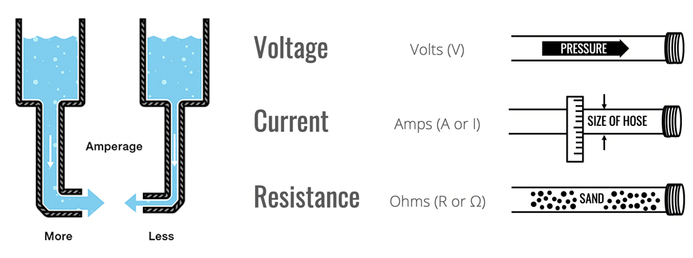
The water in the commercial-size pipe is moving much slower down the pipe to deliver the same flow rate as thinner the garden hose.
That’s because the speed at which the water moves along the hose is directly proportional to its diameter for any given flow rate. This example is exactly the same as electrons moving through a wire – the electrons need to move much faster through the thinner wire to provide the same volume out the other side.
Why does this matter? The faster the electrons have to move in the wire, the more heat they generate. So when we are pushing a very high volume of electrons through a very thin wire, they’ll still go through but they’ll generate a lot of heat because they are having to move very fast. If you ask for a lot of current and for a long period of time, that heat can get too much for the wire covering, and that is where you let the smoke out!
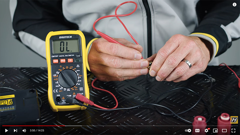
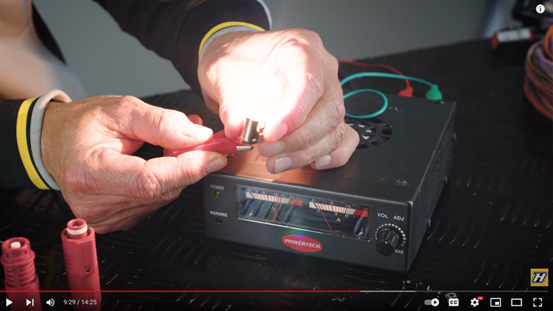
If you haven’t watched the video at the start of this article, now would be a good time to do it as it shows a practical example of this using a simple light globe.
A light globe like the one used in our video is a perfect example of leveraging the fact that when you draw enough current through a wire, it’ll heat up.
The only difference here is that we use this to our advantage in a light globe, by intentionally getting the wire red hot so that it provides us with light.
Real-World Practical Applications
Using Ohm’s Law we can calculate the expected current draw on any circuit. Armed with this information we can appropriately size the wiring to high-current devices. We also know why and how things can go pear-shaped when we undersize the wiring.
We also need to remember that just measuring the resistance of a component may not always tell us the full story about the amount of current the device will draw in real-world applications. Fuel injectors and ignition coils are switched on and off at high frequencies, so while you can measure the individual component resistance and calculate the current draw – the total current draw for the fuel or ignition system varies significantly with things like RPM and engine load.
The real-world practical application of Ohm’s Law actually requires a little more thought because it’s nuanced. The good news is, devices like the Haltech PD16 can give you real-time measurements of the actual current being drawn by a circuit and the ability to either shut it down or leave it active for a predetermined period of time. Using a device like the Haltech PD16 gives the user full control and diagnostics over the entire vehicle’s electrical system.
R5 for R35
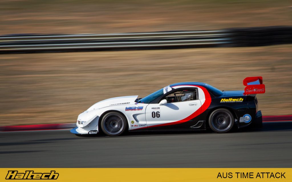
While the Nexus R5 has been quickly adopted by the drag racing and muscle car community, its advanced specs and numerous features also make it supremely suitable for circuit racing applications. We figured the best way to showcase all those features would be in a real, proper circuit racer!
It just so happened that one of our long time friends and a big time attack fan – Brian Bugh had just purchased a NEXUS R5 for his new build – a purpose built Nissan R35 GT-R race car. We have featured Brian’s other car – an LS-powered Corvette a few years ago. At the time the Corvette was competing in the Open Class at the World Time Attack Challenge and other national time attack events. The GTR will take Brian to another level with a ground up, Pro Class spec build.
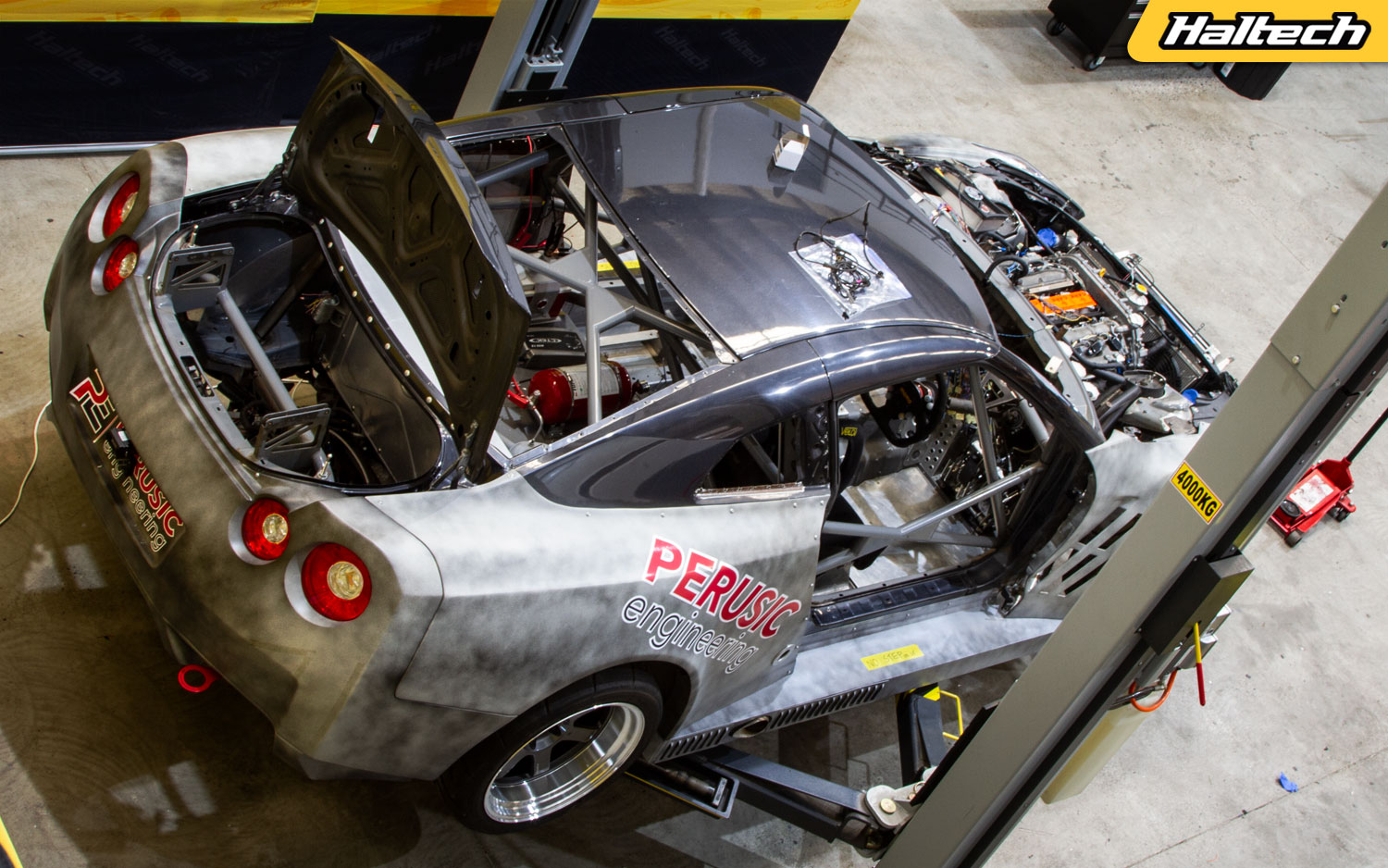
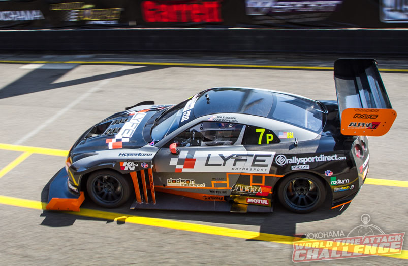
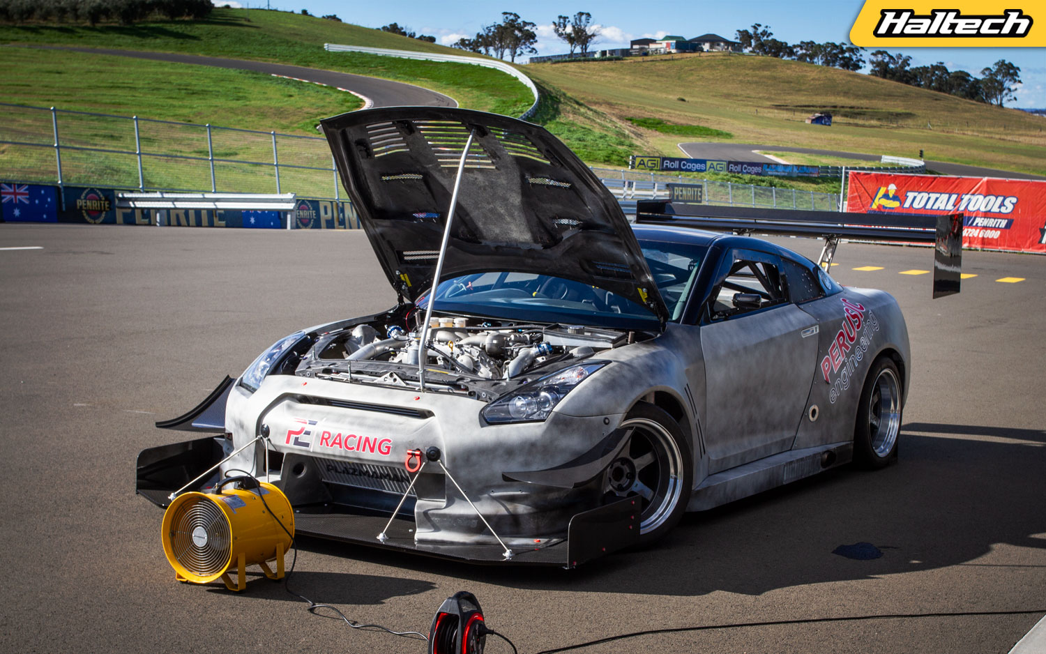
The engine currently in the car has a bit of history to it. It is this engine (albeit in a different car) that broke the HKS lap record at Sydney Motorsport Park in 2016. The engine was donated by Brian to the American team LYFE Motorsport after theirs suffered a catastrophic failure in practice. With Brian’s engine installed Cole Powelson went out and set a new R35 SMSP lap record.
Once back home in Utah, Cole and the LYFE crew pulled the engine out and shipped it back to Brian who promptly put it in its rightful place – his freshly started time attack build. Fast forward to 2020 and Brian’s car is ready for wiring and ECU install, setup and tune.

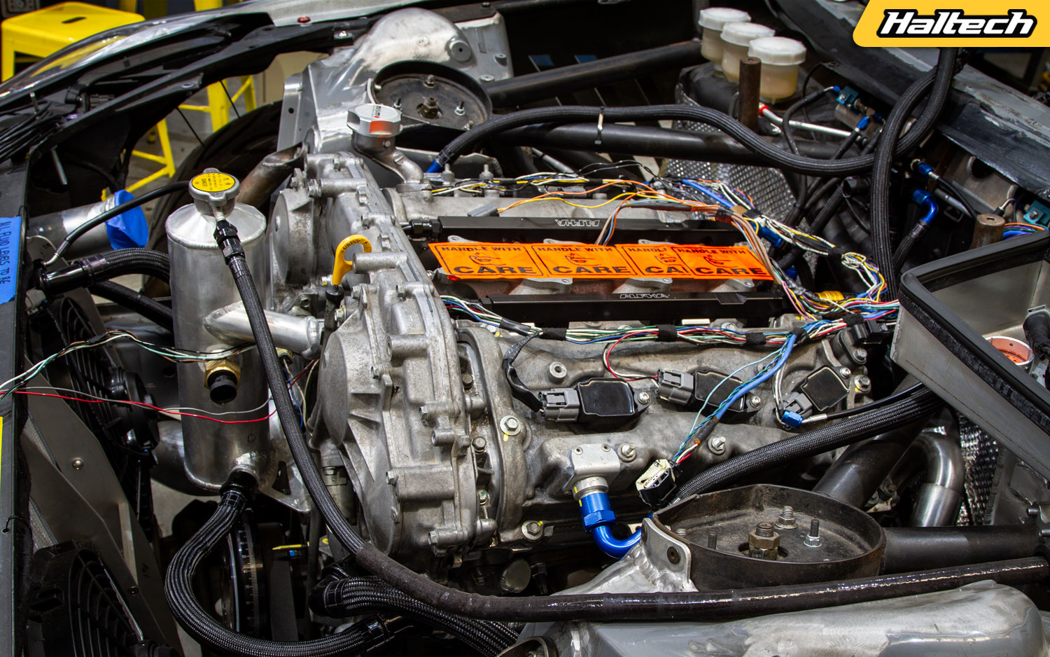
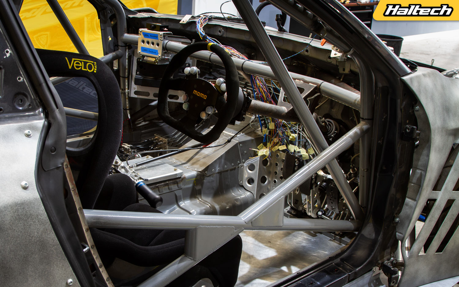
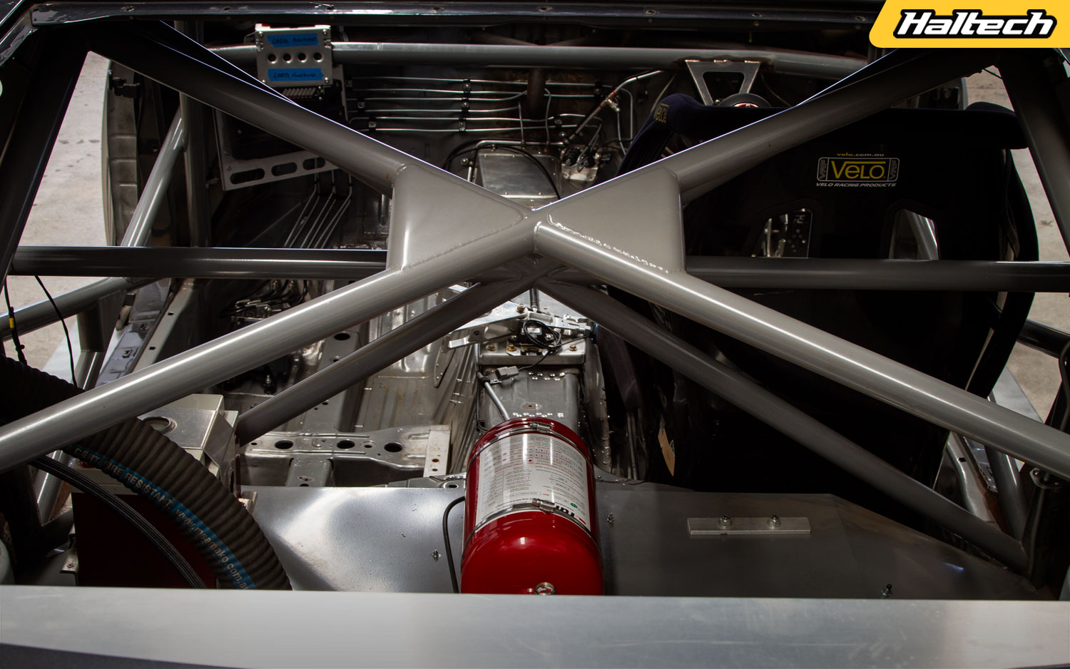
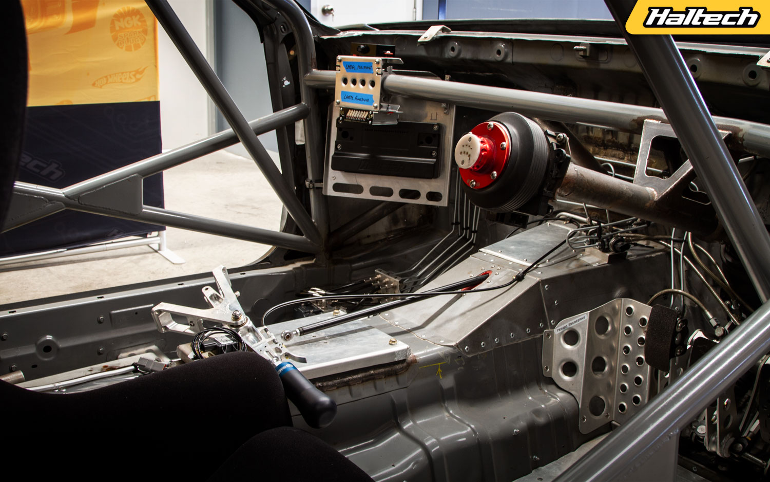
Our goal is to do a full NEXUS R5 install complete with a complete wire job. The R5 will be supplemented by a CAN Keypad, iC-7 dash, Thermocouple Amplifier and a whole bunch of sensors.
Once everything is installed we’ll go through the setup process of all the main R5 features like wire assignment, throttle blip, sequential gearbox control, traction control, rolling anti-lag, boost control and much, much more.

The next step is dyno tuning where the car will get a “soft tune” to test it for potential problems followed by a slightly less “soft” tune to get it ready for a shakedown session. The final step will involve getting the car to a race track and see how all the functions perform in their intended environment.
So get in, buckle up and hold on, it’s gonna be one hell of a ride!


Episode 1: Getting ready for NEXUS
In this episode: build overview and history, products we’ll be installing, a quick overview of NSP, wire assignment via the NSP software.
Episode 2: Wiring it all in
In this episode: NEXUS R5 wiring overview, crimping and terminated, R5, iC-7 and CAN Keypad install.
Episode 3: Configuring all the NEXUS functions
n this episode: NEXUS R5 setup including CAN Keypad config, sensor calibration, transmission and flat shift setup, final check and the first engine start!
Episode 4: Dyno Tuning
In this episode: Pre-dyno check, engine protection, oscilloscope, fuel, ignitino and variable cam mapping, boost by target gear, sequential gearbox with flat shift, pit speed limiter, solid state tuning.
Episode 5: Shakedown and Track Tuning
In this episode: Shakedown at Luddenham Raceway, data logging setup, ABS setup, pit speed limiter and traction control setup and testing.
What’s so special about Subaru’s EJ
Although Subaru didn’t invent the boxer engine, many would say they perfected it. With a long and cherished motorsport history, the Subaru EJ has collected millions of fans worldwide. Today we’re taking a deep dive to see what’s so special about the Subaru EJ platform.
History according to Subaru
The late EJ series is considered by many to be the pinnacle of Japanese boxer technology, but Subaru’s strange obsession with flat-four engines started way back in the 1960s.
Released in 1965, Subaru’s first boxer was a 900cc, water-cooled engine known as the EA-52. It made just 55hp which was actually not too bad given that it was fitted to a car that weighed only 550 kilograms.

Subaru continued to develop the boxer engine investing a considerable amount of resources into a platform that would eventually lead to the EJ. The EJ series made its debut in 1989 in the Subaru Liberty and the Subaru Legacy in the North American market. It remained in production until 2021, making it one of the longest-running production engine platforms of the modern era and was the mainstay of Subaru’s engine line.

World Rally eXperimental
It was the EJ that gave Subaru international clout powering its World Rally Championship cars, and of course we can’t talk about the EJ without mentioning the famous car it was fitted into – the mighty WRX.
In 1992 Subaru partnered up with British engineering firm ProDrive to develop a new compact chassis. Based on the existing Impreza it was dubbed WRX which stands for “World Rally Experimental” and featured a new all-wheel-drive system and a powerful, turbocharged EJ20. The engine was rated at 250hp at all four wheels although rumour has it, it actually made closer to 300hp. In the capable hands of Colin McRae, the famous 555 WRX STi went on to win the WRC constructors title for three consecutive years in ‘95, ‘96 and ‘97.


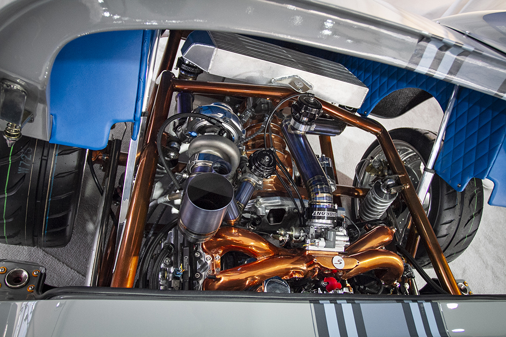
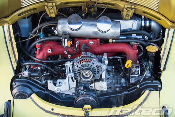
Due to their reputation as a compact, “reliable” engine platform, the EJ can be found in numerous amateur and professional motorsport series. They’ve also been a popular conversion for Volkswagen guys as a modern flat-four successor to the aging air-cooled engines, and, along the same lines are a popular engine for kit cars based on the older Porsche models.
Boxer vs Flat Four
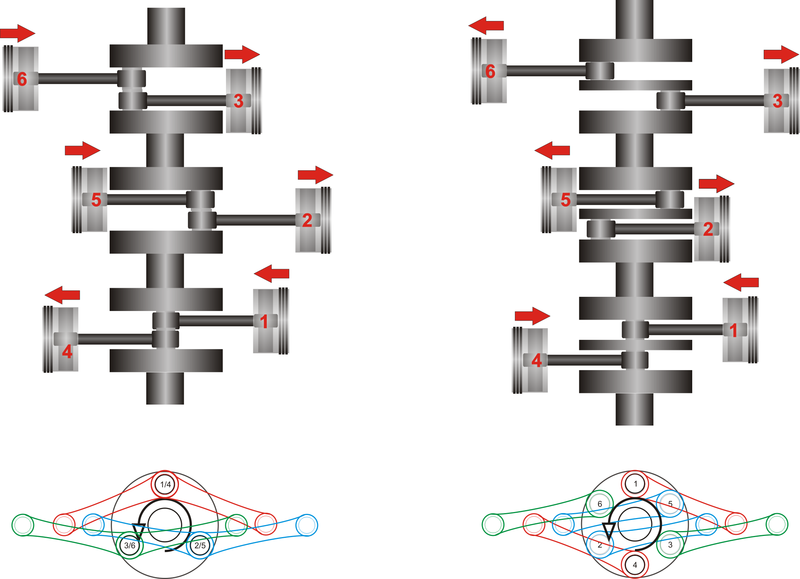
Before we go any further let’s get the definitions of a flat and a boxer engine right – because they’re not interchangeable. A boxer is a flat engine with each pair of pistons connected to a different crankpin – mirroring each other.
But not all flat engines are “boxers” because a flat engine can also have piston pairs sharing the same crankpin – working in the same fashion as any other V configuration engine.
So while all boxer engines are actually flat engines – not all flat engines are boxers.
Which one to get?
The EJ engine has been produced in over 20 variants since 1989, which means two things. There are plenty of options to suit your requirements, and depending on the model they can be plentiful and affordable. You can split most EJ engines into two groups, pre-1998 and post-1998. Both groups include naturally aspirated, and turbocharged variants.
An easy way to tell if it’s an early or later model EJ is by looking at the engine code. The earlier models end in a letter (Like EJ20G for example) while the later ones end in a number (Like EJ205). For performance builds, the most desirable EJ would probably be the EJ207. These were found in STis made in 1999 and then from 2001 to 2005. They come with a forged rotating assembly that tends to enjoy higher boost levels than the other variants.
Of course it is possible to turbocharge naturally aspirated EJs or increase the boost on turbocharged ones, but keep in mind that the cast OE pistons found in most EJs are considered a weak link and would need to be upgraded.

Popular Mods and Tuning
When it comes to modding an EJ series engine, thanks in part to the standard architecture, it’s common to mix and match blocks, cylinder heads, and rotating assemblies depending on your build. There are plenty of setups making 300 to 350hp on a stock engine, with basic bolt-on mods; but, if your horsepower aspirations are in the 400-plus region you’ll need to look at an even bigger turbo, an intercooler, upgraded fuel system, and serious engine internals upgrades including piston and conrods. While you are there a set of head studs and a quality head gasket wouldn’t hurt!
In order to control your fresh build, there are a few engine management options. Depending on the year model the Stock ECU is very “tuneable” and can work well; however, once you start to push an EJ my preference is always to move to a standalone ECU to take advantage of the engine protection strategies and to know exactly what you are adjusting in order to get a consistent and guaranteed result.
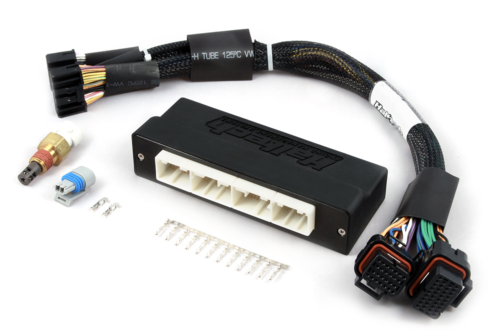
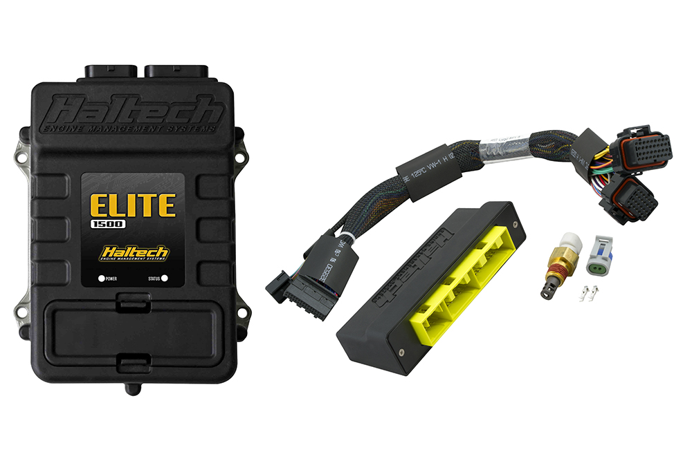
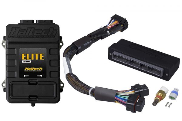
If you’re looking at a stand-alone ECU upgrade, Haltech offers a full range of “plug and play” and “wire-in” ECUs that’ll provide you with a completely programmable engine management solution. The Plug’n’Play kits come with this neat adapter box that plugs into your factory harness on one end, then, into your Haltech ECU on the other. Load the supplied base map (which is supplied with the kit) and you’re ready to hit the dyno.
Our plug-in kits cover WRXs from 1993 through to 2010; check the model compatibility list here.
Things to watch out for
Just like with any engine there are some caveats. Factory turbocharged engines have a reputation for burning oil, sticking ring lands, and if abused or mistreated; cracking pistons or worse. Remember that the WRX and STi models were sold as performance vehicles and it’s safe to assume that every one of them has had a pretty hard life.
Even the non-turbo engines will need a good check over, as the cramped engine bay of a Double overhead cam boxer makes them difficult and expensive to maintain – Doing a set of spark plugs on some of these models is an ordeal and often skipped over until there is a problem.
As mentioned earlier the factory pistons and connecting rods are considered a weak point and are commonly upgraded in performance builds, but due to the age of these engines – if it’s coming apart for any reason, it’s worth looking at a set of pistons and rods to ensure reliable operation moving forward. Some believe the factory oiling system isn’t adequate, but consult your engine builder before pulling the trigger on a high-volume oil pump as there are differing opinions here.
The Head Gasket Issue
There’s enough solid data out there to say the factory head gaskets are prone to failure at 150K to 200K kilometers.
Once again, because of its flat-four layout, replacing head gaskets on an EJ is an expensive job.
But there’s some good news! Firstly, not all EJs are heavily affected. It seems that the models most prone to head gasket failure are the EJ25s produced between 1996 and 2004. Interestingly, the problem seems to be more prevalent in the naturally aspirated and single overhead variants.
The Verdict
So, should all that stop you from getting an EJ? Let’s look at it this way – if you’re planning to put that engine in your race car then you’re probably going to upgrade the internals anyway so changing head gaskets will be a part of the job. Knowing the common issues and the limitations of what mods or fixes can be performed without removing the engine will help in planning your build. Aside from the common problems (and let’s face it, every engine has some) the EJ is a snappy and great-sounding engine with a low center of gravity.
It’s also a relatively reliable engine to use as an upgrade in your existing Subaru, an engine swap into a VW or kit car, or as a fully built monster for your dedicated race car.

Related Links:
– What’s So Special About Mitsubishi 4G63
– What’s So Special About Honda K-series
– What’s So Special about Toyota 2JZ
– What’s So Special About Nissan RB
– What’s So Special About GM LS
– What’s So Special About Ford Barra
What’s so special about Toyota’s 2JZ
Toyota has given much to the world in its devotion to automotive engineering, but few items have made as big of an impact as the JZ engine platform. Today we dive into the Japanese inline-six world and see what’s so special about the Toyota 2JZ.
The company started its life as Toyoda (spelled with a D – as it was named after its founder Sakichi Toyoda Automatic Loom Works, so they were actually manufacturing looms and sewing machines for the textile industry! That part of the business is still running to this day. The automotive part, the one that we’re interested in, didn’t kick off until the early 1930s.
The company changed its name to Toyota (with a T) in 1936. There are many theories as to why that happened but the most commonly cited one is that in Japanese, “D” is a voiceless consonant, which, apparently is not very pleasing to the ear. So it was changed to a T which according to the experts sounds “stronger” and “more pronounced”.
Toyoda released its first domestic vehicle, Model A1 in 1933. It was powered by a 3.4L, six cylinder engine producing 62 horsepower (46 kW).

Toyota Crown
Toyota began selling their first “export” vehicle in 1956 through their newly established worldwide dealer chain called “Toyopet”. That car was the Toyota Crown. Since then Toyota has grown in size and reach, surpassing GM in 2008 to become the world’s largest car manufacturer. A title it still holds to this day.


Celica Supra
Let’s turn our attention to the subject of this article and arguably Toyota’s best ever engine – the mighty 2JZ. But before we get all nitty-gritty about this famous inline-six we really should quickly talk about the hero car it powered – The Supra.
So let’s step back in time again to the 1970s. Toyota’s direct-competitor Nissan was seeing major success with its Z platform. Toyota’s own sports car – the 2000GT had been popular, but due to its limited production, it did not return a profit.


Needing to pivot quickly, the Toyota engineers stretched their existing Celica platform by nearly 130mm and elongated the engine bay to house the M series inline-six. Dubbed the Celica “Supra” (Latin for go-beyond), this would be the first of five generations of the Toyota Supra.


JZ Platform
The M-series engine went on to power three generations of Supras, but by the late 80s it was getting a bit long in the tooth, so Toyota devoted its efforts to developing a new inline-six platform. The new motor was a 24 valve, dual overhead unit, dubbed the 1JZ. It was first used in 1990 in the Supra Mark III and Crown. While it was adequate, Toyota quickly saw a need for a larger displacement JZ engine, and with reliability in mind, they created a new, taller 3.0L design.
The 2JZ that went into the 1991 Aristo was a tall-deck JZ engine that featured a shared bore and stroke, making the engine squared. Two versions of the 2JZ were made; the naturally aspirated 2JZ-GE and the more popular twin-turbocharged 2JZ-GTE. The latter, twin-turbo version finally gave Toyota an engine that could take on Nissan’s RB26 head-on.
2JZ No Shit?
Here is where things get a little odd for the 2JZ. Production variants of the fourth-generation Supra were made with both the turbo and non-turbo variants, but Toyota never officially campaigned a 2ZJ in any form of motorsport. Why?
Well, Toyota invested a considerable amount of money, time, and resources in developing an engine for their WRC effort. And since the Japanese Touring Car rules allowed any production engine to be used in their cars, Toyota opted to power their JTC Supras with the 3S-GT powerplant used in their successful WRC Celicas.

Remember the Tom’s Supra that was immortalized in Gran Turismo? Yep, that never had a 2JZ. What about the HKS Drag Supra? Well the MKIII ran a 7M, and the MKIV used a UZ-based V8.


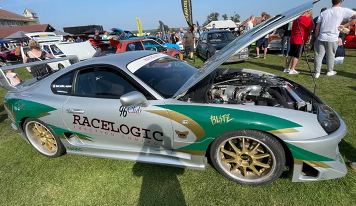
It wasn’t until a few years into the Mark Four Supra production run that privateers began campaigning and developing the 2JZ platform. Notably, the Blitz Tuning Supra tackled the Nurburgring modified production car record and claimed the title in 1997 with their impressive 7-minute 49-second run.

But no one could have expected that a street racing film from America, would make the MKIV Supra and the 2JZ one of the most popular engines in the world. Jokes aside, this film and the explosion of drifting as motorsport helped grow the aftermarket into what we know today.
Which one to get?
The 2JZ as mentioned came in two variants, the naturally aspirated GE powered the MKIV Supra, Aristo, Crown, Chaser, and Soarer chassis respectively. It uses sequential fuel injection, with an aluminium head using four valves per cylinder. It also used a DIS ignition system, but it did not use a coil on plug setup but rather used a coil for every two cylinders. In 1997, they were upgraded to variable valve timing and remained that way through the end of production.
The GTE model was a direct competitor to the popular Nissan RB26DETT, featuring an air-intercooled, twin-turbocharged induction system. The block, crankshaft, and connecting rods are shared with the GE, however, a new high-flowing aluminium cylinder head was developed alongside new, larger valves and higher duration camshafts.
The biggest difference aside from the cylinder head are the oil spray nozzles installed to help lubricate the engine under the increased load. This and the shorter piston to lower compression ratio makes them a much more desirable option for the average enthusiast. Again, like the GE, variable valve timing was added in 1997.


Modding and tuning the 2JZ
While the 3.0L inline makes respectable power in stock form, many owners seek out more power by replacing the factory turbochargers. Ditching the restrictive factory exhaust manifold and turbocharger (usually in favour of a larger single setup) can easily bump up the power output. Whether or not you choose to try and modify the stock ECU is up to you, but considering we have been in the engine management business for nearly 40 years, we would highly recommend ditching that old, archaic system.
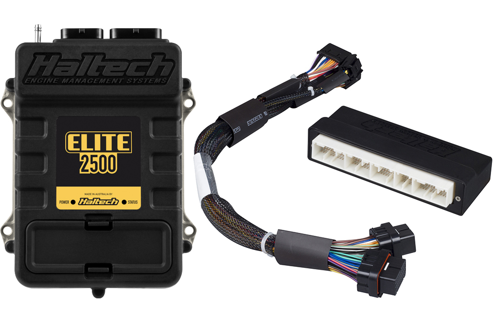
At Haltech, we have developed a complete replacement engine harness that suits our Elite 2500 ECUs. If you’re looking for something simpler, we even offer a plug and play adapter for the MKIV Supra that uses your existing wire loom and installs a new Elite 2500 ECU. This plug-and-play adapter is a great alternative for light or heavily modified cars that are not using variable valve timing.


Things to watch out for
The valve guide seals are known to fail pretty early on, but there are aftermarket options to help remedy that. Look for smoke out of the exhaust on startup, that’s usually a good indicator. If you’re considering a VVT model, look for sludge in the valve covers, this will be especially bad if the VVTi cam gear is leaking. Another potential issue would be sludge or oil debris clogging the VVT solenoid (oil control valve) screen.
All in all, these 2JZ engines, if pulled from a wrecker with good service history, should be a great option to swap into your project car.


Fuel For Thought
Petrol/Gasoline, Ethanol and Methanol – they’re all just fuels right? RONs, MONs, octane ratings, additives, combustion points and alcohols – in this article we are going to cover the different types of fuel we use in our internal combustion engines, the effects these fuels have on power, and how we might adjust an engine’s tune-up based on the fuel being used.
Octane Rating
Before we get too deep into the weeds here, we need to get some terminology squared away, probably the most common piece of fuel information that most people have heard of is octane rating. There are a couple of different ways of measuring the octane of fuel. Whether it is the RON (which stands for Research Octane Number) or the MON (which stands for the Motor Octane Number) both are a measure of fuel’s resistance to detonation. The higher the octane rating, the less likely the fuel is to detonate at any given temperature and pressure.
Alcohol
The two most common types of alcohol fuels are Ethanol and Methanol. While these 2 different fuels have similar names, chemically they are quite different. Both are alcohol fuels but Ethanol has twice as many carbon atoms as methanol in its chemical makeup.

Gasoline/Petrol
Petroleum-based fuels are the most common fuels we find at pumps and are made up of a complex mixture of hydrocarbon compounds. They are typically made by refining oil that has been pulled out of the ground and are available at just about every fuel pump across the globe.
These fuels come in both standard and a high octane blend, with the high octane varieties costing a few cents a liter or gallon more than their lower octane counterparts. It is these refined oil-based fuels that we are going to use as our base to compare all other fuels against today.

More Octane – More Better?
So what is the actual difference between lower octane and higher octane fuels at the pump, and, more importantly, which should you use in your engine?
The main difference is on the label – the Octane rating gives us an indication of the fuel’s combustion point but there’s more to it than that. It’s important to know how a fuel arrives at this increased octane rating, and that’s dependent on a lot of factors like the base oil stock, the refining process, the additives used in the process, and even the location of the end product. If you want to dig deeper on this topic check out this excellent article Where Does Gasoline Come From.
The important thing to remember is that Octane rating is simply a rating of a fuel’s ability to resist detonation at a given temperature and pressure. Why is this information important to us? When we are building an engine, the higher the compression ratio the engine is, the more pressure is built up in the combustion chamber on the compression stroke.
If we increase the compression ratio enough – we will build up so much cylinder pressure the air and fuel reach their auto-ignition temperature and pressure either just prior to or just after the spark plug firing (detonation).
The important detail to know is cheaper (or should we say “less expensive” given current fuel prices), lower octane fuels reach their detonation point at a lower temperature and pressure than the higher octane fuels. What does all this mean in the real world? It means the higher compression ratio your engine runs, the higher octane fuel you will need to use.
It’s the same rule with turbo or supercharging because turbos and superchargers increase the air pressure in the intake manifold and therefore the combustion chamber, so the more boost you are running the higher octane fuel you need to run to prevent detonation.
What about low compression engines?
If you have a relatively low compression ratio, naturally aspirated engine, or a stock daily, is there any benefit to running high octane fuel? Honestly, no, there isn’t. If an 87 octane fuel is not reaching its detonation point in any of the operating conditions of your engine, the only performance gain that will be made by running a higher octane pump fuel in that engine – is the performance of the fuel company’s stock price.
When you book a trip to the dyno to have your car tuned, make sure you fill the tank with whatever fuel you are going to run consistently.
There is no use going to the dyno with your own custom blend of 98, moonshine and rocket fuel octane boosters, if you can’t get the fuel again. The guy tuning your engine is going to tune it to the fuel that’s in the tank – if you turn around the next day and put whatever low dollar sludge you can find into the tank – chances are the engine is going to ping iteself to death.

Changing Fuels
What happens if your car is tuned on 98 or 95 but when you’re out on a road trip you simply can’t get it. Don’t worry, a tank or two of lower octane fuel isn’t going to cause the conrods to escape out the side of the block. If you can’t get high octane fuel, just fill the tank with what you can get and drive accordingly, so no limiter banging, no hitting boost cut, and no track days if you can’t get the quality of fuel that your engine is tuned for.
Another option, if you’re using a Haltech ECU, is setting up dual maps or an ignition trim that will switch between ignition timing or boost maps on low and high octane fuels.
Beautiful Blends
Let’s move on to petroleum-based fuels that have ethanol mixed with them. Fuels like E10 are inexpensive, but seem to have a slightly higher octane rating than the other fuels. The reason for that is the Ethanol content (that’s what the 10 stands for) 10% of the fuel is actually Ethanol.
Ethanol as an alcohol-based fuel for the most part has likely been manufactured using sugar from either cane or corn. The great thing about these alcohol-based fuels is they have really high octane ratings in excess of 110 Octane for Ethanol. So mixing just 10% of ethanol into a petroleum fuel will often bump the octane rating up a 2 or 3 points.
What about E85 or fuels that are 85% Ethanol and only 15% Petroleum – are these fuels really over 110 Octane? In short, yes. But that’s not the only benefit of running E85. Because E85 has a different stoichiometric air to fuel ratio to petrol or gasoline, we need to provide the engine with roughly 30% more E85 to meet the same stoichiometric air to fuel ratio that we would have on gasoline.
That’s important for two reasons, first – we can’t just fill up any vehicle with E85 and expect the engine to run correctly. If you want to run E85, the ECU will need to be programmed to suit – fortunately, that’s really easy with all modern Haltech ECUs and with the help of a Flex Fuel sensor it’s almost completely seamless.
Secondly, that extra fuel that we add to the intake actually starts to have a significant cooling effect on the incoming air stream. What this means for turbocharged or supercharged engines is not only does E85 have a high resistance to knock – but it also cools the incoming air. It’s like having a mini intercooler!
Methanol
No discussion on alcohol fuels would be complete without talking about the big daddy of alcohol race fuels – Methanol. The most important thing about Methanol is its octane rating – it’s almost too high to measure, which is exactly why when you want to run 120psi of boost and 11,000RPM on your fire breathing drag car – the only fuel you even attempt to use is Methanol.
Methanol fuels have a stoichiometric air-fuel ratio around the 6.5:1 mark, which in round terms means we need to run twice as much methanol than we would gasoline to maintain the same chemical relationship of air and fuel in an engine. All that extra fuel means more cooling of the intake charge and cooler air is denser, and dense air equals horsepower.
Horses for courses
So why aren’t we all just running methanol in our daily drivers? Well, technically we could – but while Methanol is a great race fuel, it’s also a great solvent and reacts with many organic compounds so components like rubbers, seals and alloys of aluminium can all be damaged by methanol.
Methanol racers know this and they take great care to flush out the fuel lines, clean their fuel injectors, replace their fuel filters, and the like on a regular basis. So while Methanol is a fantastic fuel for high power, big boost engines, it requires a lot of upkeep and maintenance.
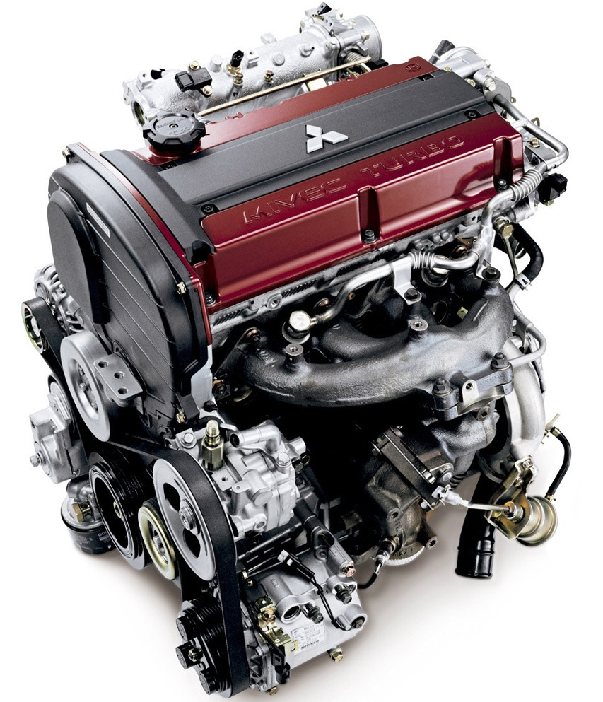
What’s so special about Mitsubishi 4G63
Manufacturing everything from air conditioners, forklift trucks, hydraulic equipment, power generators, printing machines, ships, aircraft, and even railway systems, Mitsubishi shied away from mainstream motorsport until the 1960s.
But it was in the 1980s that the Japanese car maker made its mark on our industry with its factory backed World Rally Championship program and its unmistakable performance platform – the 4G63.
First introduced IN 1980 as a four-cylinder, 2.0-litre, petrol powered, naturally aspirated engine, The 4G63 is a member of the Mitsubishi Sirius 4G6 family.
But today we are looking at its more potent and infinitely more popular version – the turbocharged 4G63T.
Brief History
The 4G63T was first seen in the 1988 Mitsubishi Galant VR-4, then later in the more performance focused Evolution Lancer.


In North America the 4G63 was available in the higher trim levels of the first and second generation Diamond Star Motors cars, or DSMs for short. These were a series of sport compact coupes wearing Mitsubishi, Eagle or Plymouth badging.
During the late 1980s the 4G63 equipped Group-A Galant VR-4 carried Mitsubishi to its first outright World Rally Championship victories.

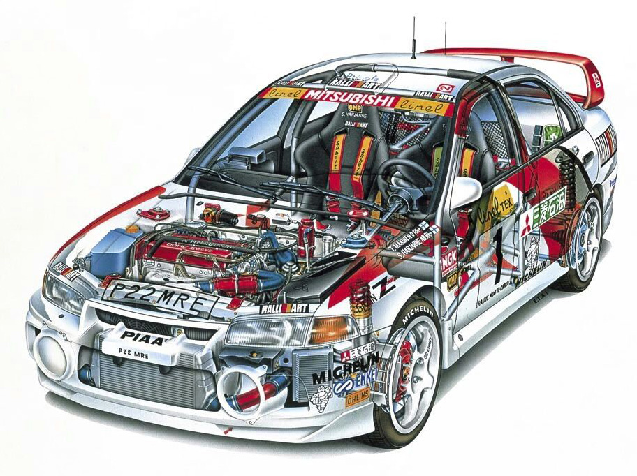

Mitsubishi then homologated the Group-A Lancer Evolution, and, in the hands of Finland’s Tommi Mäkinen, won the drivers’ title four years in a row (from 1996–1999), and, won the manufacturers’ championship in 1998.
The Lancer Evo also dominated the Group-N FIA championship for showroom-ready race cars, winning seven consecutive titles with four different drivers from 1995–2001. Even in 2002, when Mitsubishi came second to Proton in the Group-N rally, it was a 4G63 that powered the Proton to victory!
Mitsubishi’s mainly been associated with rally and circuit racing, but in the last 15 years, the 4G63 engine’s played a huge role in Mitsubishi-powered drag racing vehicles as well.
With each passing year, new records are set and the mighty 4G63 surprises us with times that we never thought would be possible from a 4-cylinder engine.
In the United States, names like David Buschur and John Shepherd pioneered the development of DSMs and the 4G63 for drag racing purposes.
Haltech heroes like Aaron Gregory and Devin Schultz are carrying the proverbial torch with machines that clock off consistent 7 and 8 second ¼ mile times at over 200mph!

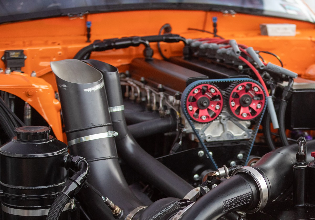
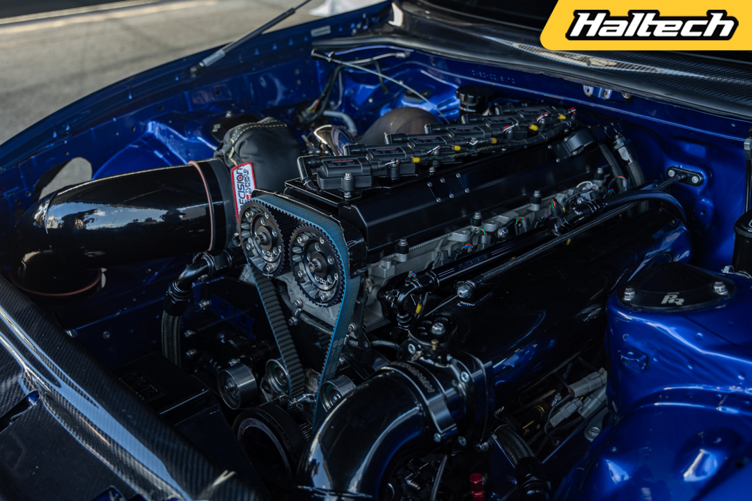
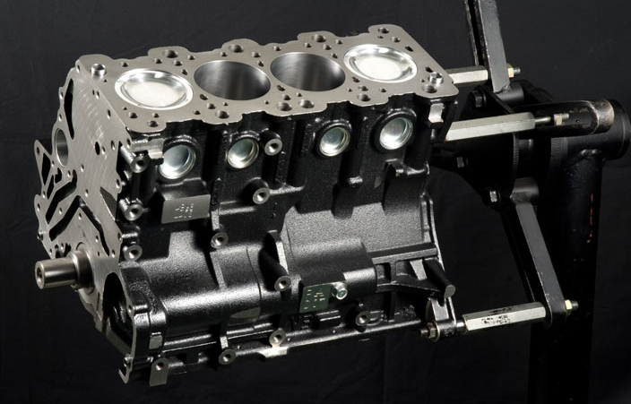
Engine Overview
The 4G63 engine uses a cast iron cylinder block and aluminum cylinder head. The engine block houses a forged steel crankshaft and connecting rods, while the pistons are cast aluminum. They use a timing belt (not a chain) to link the crankshaft to the cam gears.
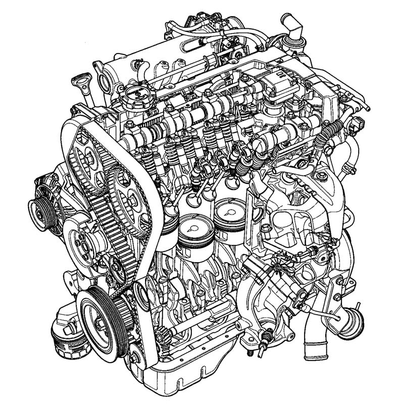
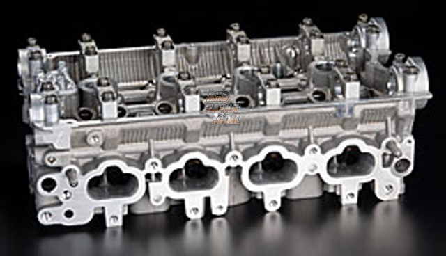
Depending on the variant of 4G engine, they’ve got several different aluminum cylinder heads: a low performing 8-valve single overhead cam head, a better 16-valve single overhead cam head, and the best 16-valve dual overhead cam head – which is also available in different Big and Small port versions.
The single cam head actuates the intake and exhaust valves via rocker arms and the adjustment of the valve clearances is required. The cylinder heads with dual overhead camshafts have been available since 1987. These engines also have rocker arms but with automatic hydraulic valve clearance compensation.
Like Honda’s B and K series engines, the 4G63’s head and block were interchangeable with its longer-stroke sibling, the 4G64 – Combinations of these two engines can yield displacement increases of up to 2.4 liters.
The 4G63 can still be found in production vehicles today. This means an overwhelming 40 year production lifespan for the little Mitsubishi platform. To add to that, aftermarket support and development are still going strong.
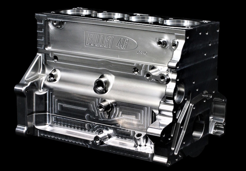
With each evolution of the engine, newer technology and more factory horsepower have been added. The high-flowing aluminum cylinder head and stout iron block now form the foundation for high power production with some examples exceeding 1,000 horsepower and billet block engines have been capable of up to 1700hp.
Things to watch out for
The 4G63 block comes in two variations. 6-bolt and 7-bolt. This refers to the number of bolts holding the flywheel to the crankshaft but is indicative of many other differences throughout the engine. Most notably, the 7-bolt main bearings have narrower journals and are allegedly not as strong as 6-bolt engines, therefore they have become less desirable for high-horsepower builds.
The 7-bolt engines also have a tendency for developing “crank walk” which is when the thrust bearing on the crankshaft deteriorates rapidly, causing big problems in the bottom end as it fails. A point of contention among enthusiasts is that the 7-bolt is not automatically more prone to crank walk and that 7-bolt crank walk’s little more than an internet talk.
Regardless, when purchasing any 4G63 second hand, it’s important to check the crankshaft for play in order to identify an engine that may have a worn thrust bearing and the beginnings of the dreaded “crank walk”.
The 4G63 is originally equipped with balance shafts that are driven by a secondary, rear timing belt. This belt’s prone to breaking and causing primary timing belt failure and resulting in catastrophic engine failure. Deleting these balance shafts and their timing belt is normally one of the first steps any performance minded 4G63 owner takes.
But there is a downside to this – the balance shaft does noticeably reduce engine vibration at idle and cruise speeds, a small sacrifice in a performance engine build.
Tuning options
Haltech ECUs support all forms of 4G63 factory trigger patterns. This includes Evo 1 through to Evo 9 and 1G or 2G DSM as well as the most popular aftermarket crank and cam pickup options on the market.
We also manufacture 4G63 terminated engine harness kits to suit the 1G and 2G DSM configurations as well as Elite-spec Plug’n’Play adaptors to suit EVO 1 to 9. Basically, if you’ve got a 4G63 we can control it, and we can control it well. They’ve been the heart of many of our personal project cars and development cars – an engine close to our hearts!
Related Links:
Micks Motorsports 1200hp, 8sec Evo
Aaron Gregory’s 7sec Eagle Talon
Shop for Mitsubishi Plug’n’Play ECU systems
Throttle Pump Explained
In this article we are unraveling one of the mysteries of tuning; the often talked about but rarely understood dark art of tuning the Throttle Pump, or as we call it here at Haltech the Transient Throttle Enrichment function.
If you have even a passing interest in engine tuning you have probably come across a vehicle or engine that runs fairly well under steady-state conditions at all load and RPM areas, but when you mash the throttle quickly the engine coughs a splutters before eventually taking off again. The most likely explanation for that happening is the incorrect setup of the transient throttle enrichment.
IT’S ALL IN THE NAME
Don’t be too worried if you are unfamiliar with the term “Transient Throttle Enrichment” this feature goes by a few different names. If you come from the carburetor world you probably know this term as the Accelerator Pump or Accelerator Enrichment Valve. It’s also known as the Throttle Pump, or the Fuel Tip In, or Throttle Tip In.
These terms all refer to the same thing, and in the Haltech software we call it the Transient Throttle Enrichment function.
Let’s start by explaining what the transient throttle enrichment is and why we need it – because this will set us up for a good understanding of how to approach the tuning process.
The Carburetor Conundrum
If we cast our minds back to the yee ole days of carburetors you will notice that in every carb there is a fuel circuit that is activated purely by moving the throttle. The way it works is irrespective of the amount of air moving through the carburetor, simply when you move the throttle you get an extra spray of fuel. The accelerator enrichment circuit in a carb is an intricate balance of springs, pistons, and valves.
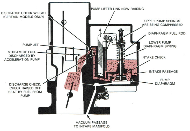
If you have ever had the acceleration enrichment circuit clog up and stop working on your carb you will know what happens next. The engine starts and runs just fine and so long as you are real gentle on the throttle, everything is good – but stand on the throttle quickly and the engine has a massive lean spot, it hesitates it often misfires and occasionally backfires through the intake.
What we’re experiencing there is a big lean spot, the engine is running fine until you mash the throttle, and then it goes lean. Why? It’s all about physics – in a carburetor the air and the fuel are both injected into the intake manifold at the same spot – the carburetor.
What happens when you mash your right foot to the floor and the throttle blades slam open is you get a big gulp of air rushing into the intake manifold. However, and here comes the physics, air is approximately 600 times lighter than fuel, so when you get a rush of air into the intake – the air makes its way to the intake valve and combustion chamber 600 times faster than the same mass of fuel.
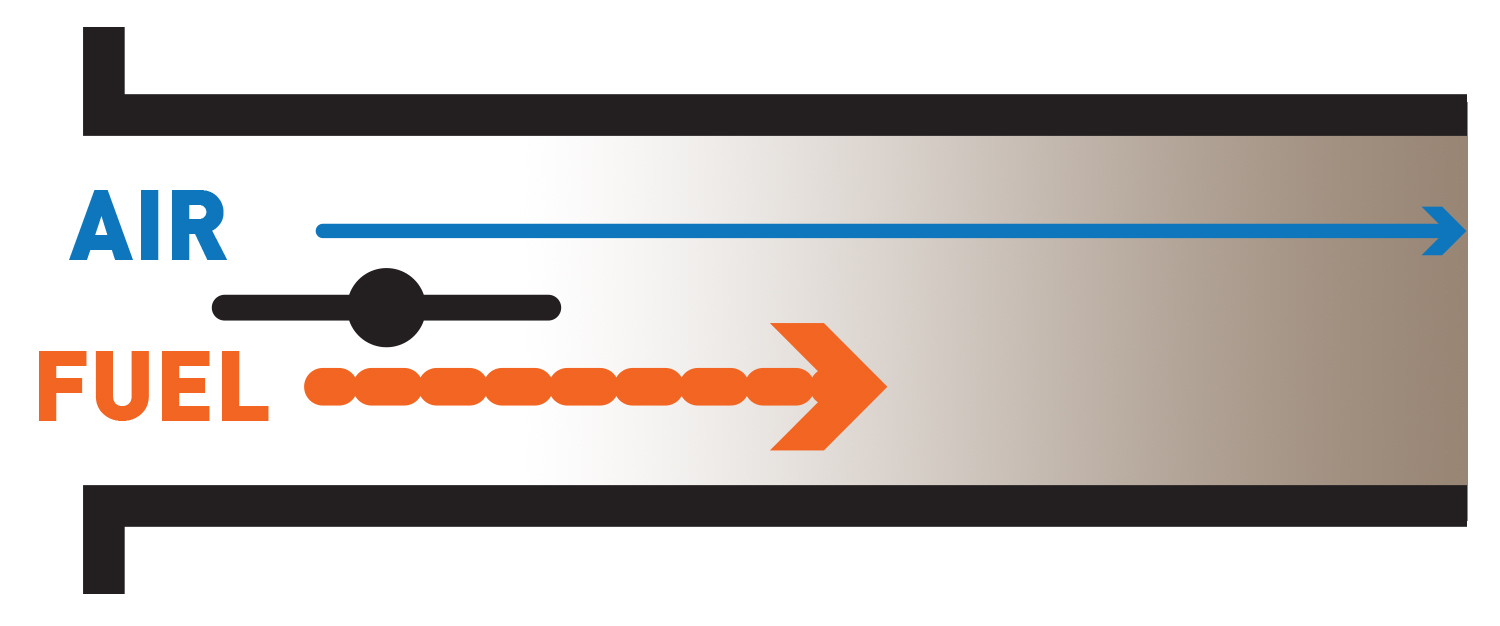
So the next time the valve opens, the air rushes in, the fuel hasn’t yet caught up, the valve closes, we get compression and spark but no bang. This happens for a couple of engine cycles until the fuel finally decides to show up to the party and we start making fire again.
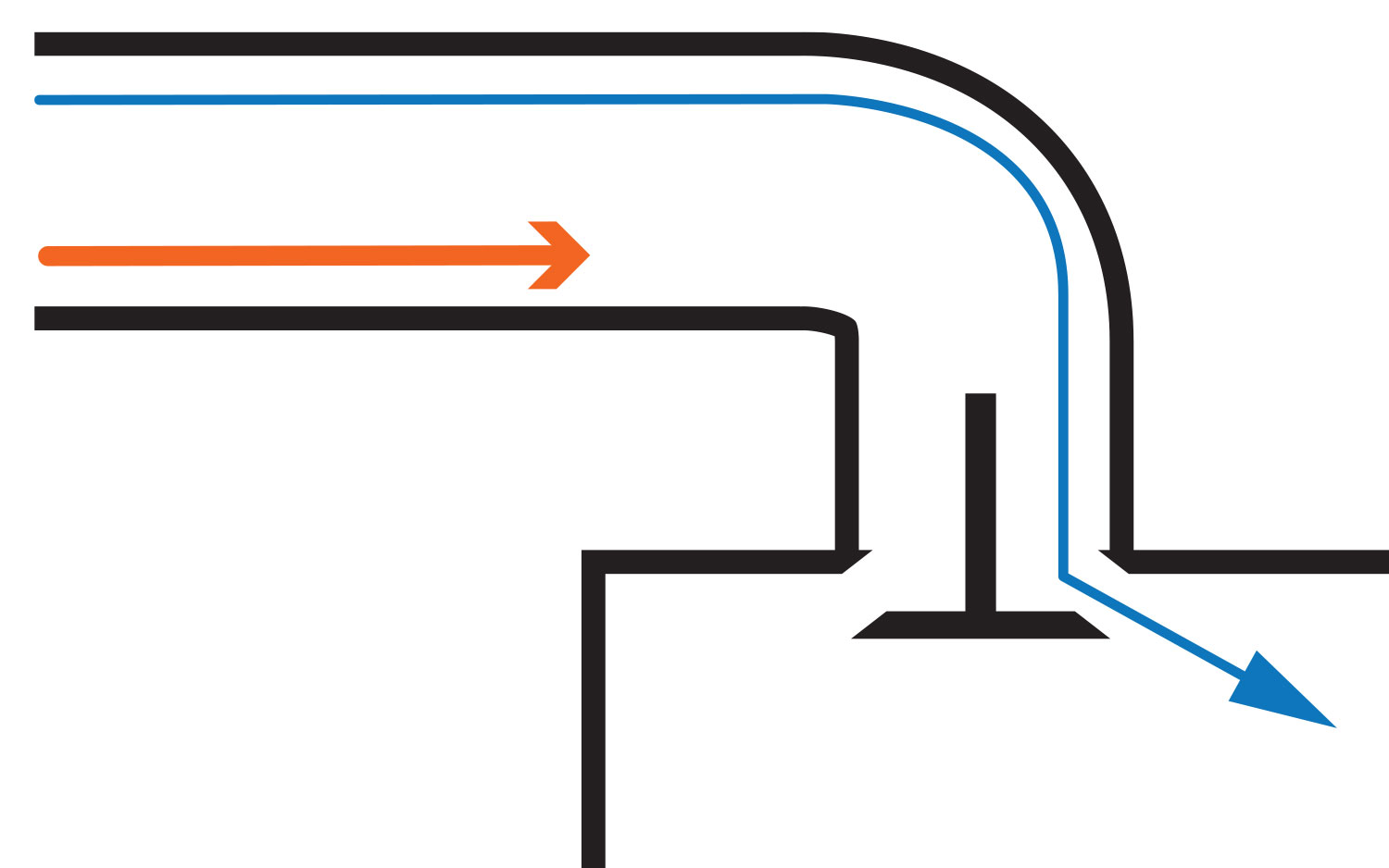

The throttle pump circuit on your carb is designed purely to try and give that fat, lazy, heavy fuel a head start in the race to the intake valve in the hope that some of it makes it there in time for the intake valve opening.
If you put an air-fuel ratio meter on a carburettor-controlled engine, you will notice that even the most finely tuned carb will always have a lean spike followed by a long rich tail on acceleration. You get the rich tail because the regular fuel delivery eventually catches up with the additional fuel in the acceleration enrichment event and the engine runs rich.
What about EFI systems?
EFI systems remove one of limitations found on a carburetor that cause this phenomenon – the fact that air and fuel are both coming into the intake at the same place. Typically we find EFI fuel injectors located much closer to the intake valve than the throttle body – so effectively the fuel has a massive head start in the race to the valve.
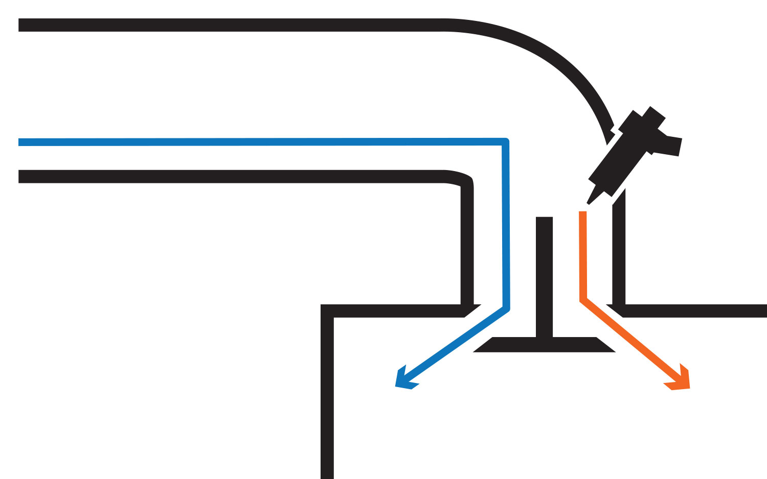
The second advantage we have with EFI is the pressure under which we are injecting the fuel. With an additional 40PSI of pressure pushing the fuel toward the valve, we are roll racing fuel and air rather than drag racing them as in the carbureted system. Finally, most modern injectors do a really good job of atomising the fuel into very fine droplets, so they can accelerate very quickly.
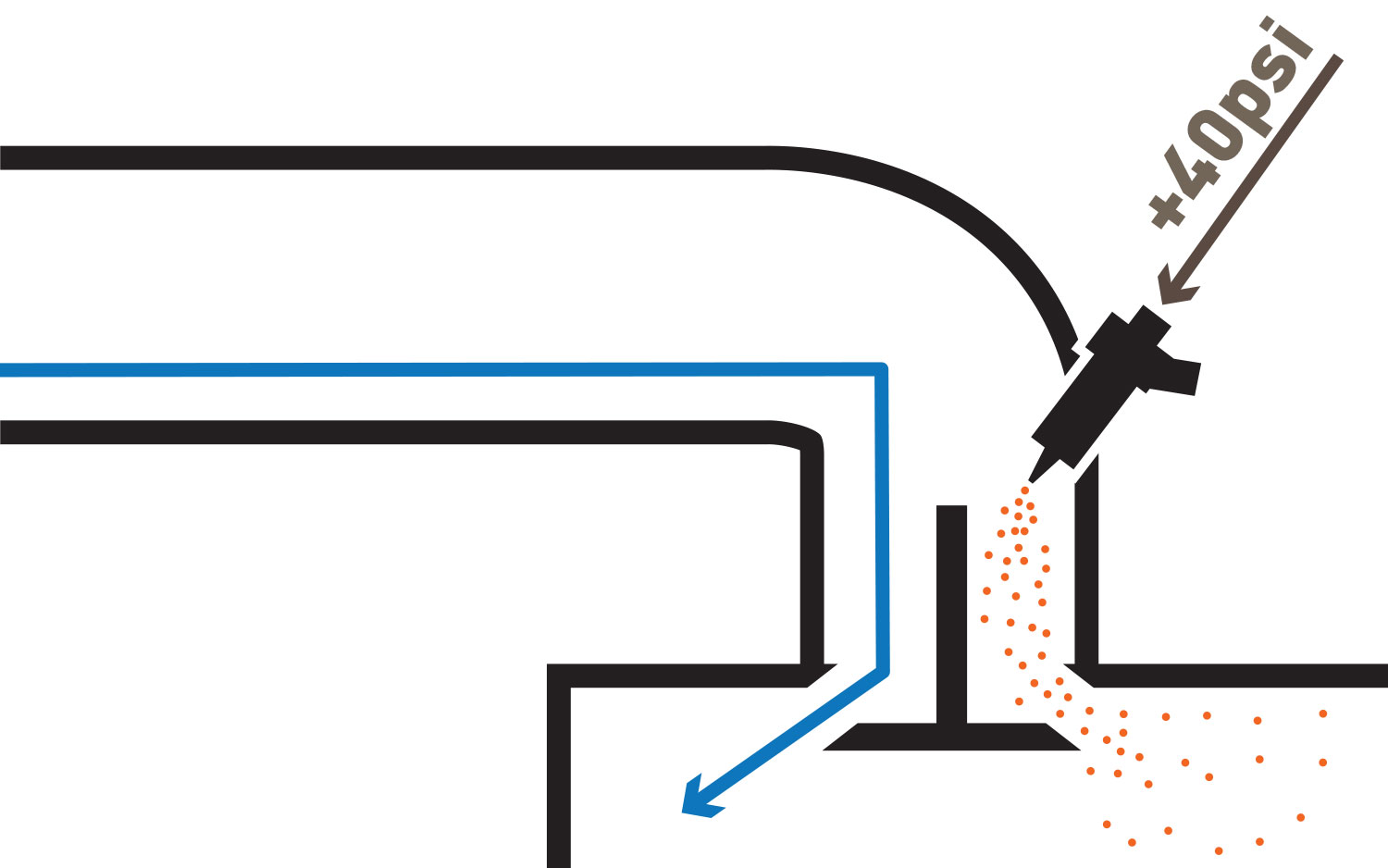
What all that means is that in most cases we need a lot less additional fuel to be added to the intake manifold when the throttle is snapped.
NOTE:
We say “in most cases” because there are always exceptions. If you are running a throttle body injection setup you tend to find you still need to provide a lot of addition fuel in the transient throttle enrichment because you are dealing with the same limitation that a carburettor is. The fuel is still much heavier than the air and because it’s a throttle body injection setup the fuel and air are being injected at the same spot so we need to throw much more fuel at the race as early as possible to try and prevent the engine from misfiring.
Another advantage of an EFI system is the ability to use sequential fuel injection and being able to time fuel delivery event with the valve opening. We won’t go too deep into this here because it’s a topic that requires its own article but we the basic premise here is injection timing – that is when the fuel is injected (rather than how much fuel is injected), often plays a big part in the overall vehicle driveability which includes the transient throttle enrichment.
Our suggestion is that you don’t put too much effort into tuning the transient throttle enrichment until after you are happy with the tune-up on all of your steady-state fuel maps, which includes the injection angle map.
For a step-by-step Transient Throttle Enrichment setup in the Haltech tuning software watch the video at the top of this page.
How O2 Wideband Controllers work
It cannot be overstated just how important it is to get reliable and accurate data from your wideband air-fuel ratio meter. And while there is a multitude of different wideband O2 sensors on the market and they don’t all play nicely together.
You can’t, for example, take a Bosch sensor and use it with an NTK controller or vice versa. In fact, you cannot even take two series of Bosch sensors like the Bosch LSU 4.2 and the Bosch LSU 4.9 sensor and use them with the same controller. Your wideband controller must be matched with the specific sensor type it was designed for.
Before discussing the different types of sensors, let’s start at the beginning and look at what narrowband and wideband sensors are and how they work.
Narrowband O2 Sensors
Narrowband O2 sensors typically have either 1,2,3 or 4 wires and they all work basically the same way; the output signal will flip from 0V to 1V when the air-fuel ratio goes richer than the stoichiometric air to fuel ratio of 14.7:1, it then flips back to 0V when the measured air-fuel ratio goes leaner than the stoichiometric air-fuel ratio of 14.7:1 or lambda of 1.
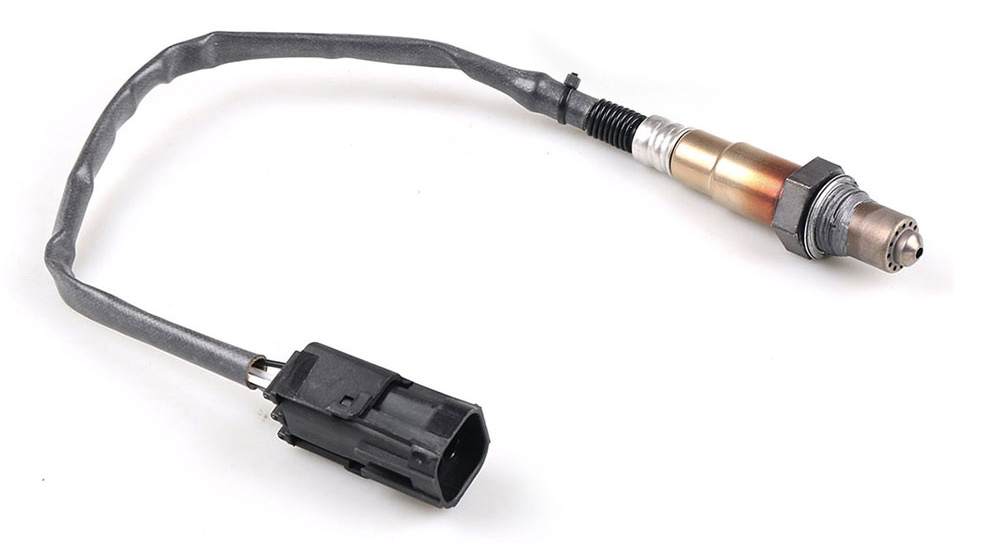
This is important to know – because it means a Narrowband O2 sensor does not know and cannot tell you if an engine is at 13:1 air-fuel ratio, 12:1, 14:1, or any specific air-fuel ratio for that matter. It only knows 2 values: lean of the stoichiometric air-fuel ratio and lean of the stoichiometric air-fuel ratio.

TIP: If you have not watched our on Ignition Timing vs Air-Fuel Ratio’s effect on output power – now is probably a good time do it because in that video we explain why selecting the correct air-fuel ratio is so important (spoiler alert: it’s much less about making horsepower and much more about engine longevity).
So, if a Narrowband O2 sensor cannot tell us any specific air to fuel ratios (apart from 14.7:1) and we know that running an engine at full noise with an air-fuel ratio of 14.7:1 is potentially catastrophic – then what are narrowband O2 sensors for?
The simple answer to that question is “tailpipe emissions”. We are not going to go into detail on how to tune an engine to meet specific emissions standards here, but broadly speaking to pass most emissions tests you need a catalytic converter in your exhaust. A catalytic converter is made up of multiple materials each with the specific purpose of converting potentially harmful byproducts of combustion into harmless carbon dioxide, water, or Nitrogen. For the catalytic converter to work effectively it must be receiving a pulsating exhaust gas flow of mixtures rich and then lean of stoichiometry.
Incidentally, this is exactly why in years gone by manufacturers would turn off O2 control under full engine load and high RPM. Not because the engine would make less power, but rather for the O2 control to work it relied on the air-fuel ratio oscillating around 14.7:1 which is far too lean for engine reliability at high horsepower. What the O2 narrowband sensors are not useful for – is tuning an engine.
Wideband O2 Sensors
Wideband O2 sensors typically have 5 or 6 wires and require some very specific electronic circuitry to control them. When controlled correctly wideband O2 sensors are capable of accurately showing air-fuel ratios anywhere from 6:1 to over 20:1 which makes them the only choice for measuring air-fuel ratio when tuning an engine.
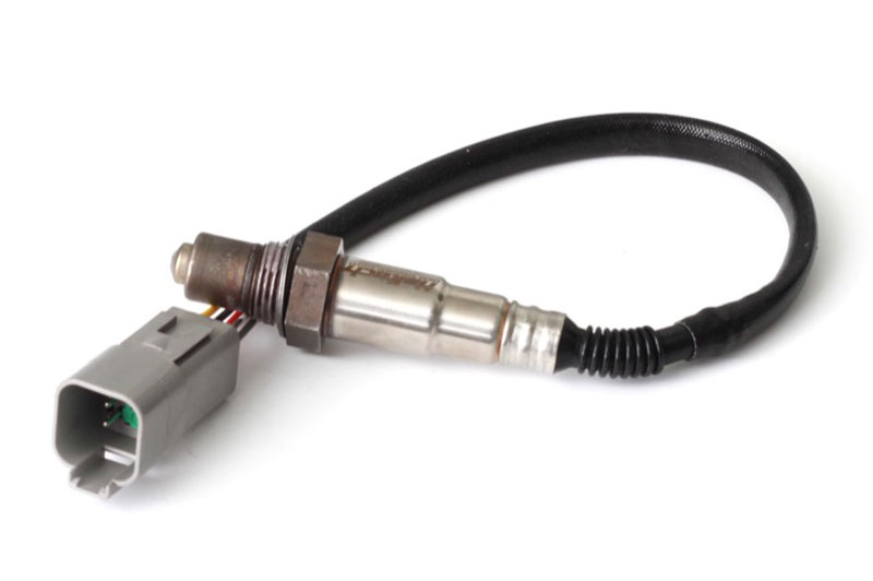
With a wideband O2 sensor the ECU can be monitoring the actual air/fuel ratio, checking back against the tuner’s desired ratio, and then make changes to make sure the Target and Actual are always the same. We can even perform what we call “Long Term Learning” so that each time the Target and Actual Air/fuel ratios don’t match the ECU will record and apply a correction. This way the ECU is not trying to correct the same error over and over again. And the best thing is – as you drive the car the tune gets better and better!
Why would there be an error you ask? This could be down to different climatic conditions like temperatures and pressure, it could be related to fuel temperature, intercooler efficiency on the dyno compared to on the road or parts of the fuel map that are hard to simulate on a dyno.
It would be a hugely time-consuming task to tune for every potential temperature for every sensor on every custom modified engine, and it’s for this exact reason why a wideband oxygen sensor and long-term fuel learning are a must for a performance car.
With a wideband Oxygen sensor, you can also set operating limits to protect the engine. For example, if the RPM was higher than 4000 and the boost pressure is higher than 15 pounds you could set an Engine Protection Limp State if the AFR is leaner than say 13:1 (or whatever you choose).
This, coupled with the increased fuel economy and performance that Closed Loop O2 control offers makes choosing a wideband oxygen sensor the obvious choice.
Haltech O2 Wideband Kits
Let’s take a look at Haltech’s current offering of Wideband O2 sensors, the most common of which is a CAN-connected wideband unit.
This unit uses a Bosch LSU 4.9 wideband O2 sensor and has been the mainstay of Haltech’s wideband o2 controller offerings for a number of years. It’s safe to say it’s one of the most tried and true wideband O2 sensors and controllers on the market today. It readily and repeatedly reads air-fuel ratios down to 10.5:1 and when installed correctly has a long sensor life on most fuel types.
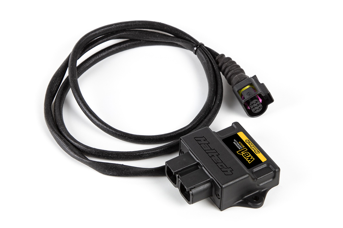
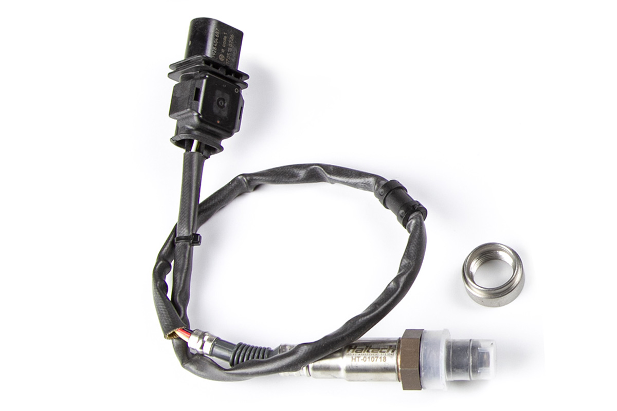
Note we said “most” fuel types and not “all”. That’s because the fuel type is one of the limiting factors of these sensors. Fuels that are not petrol or gasoline and air-fuel ratios that are richer than 0.7 lambda can significantly shorten a Bosch LSU 4.9 sensor life.
And that is where the NTK sensors take over. The NTK LZA08 sensor offers a much more robust sensor life at both richer mixtures and with alternate fuel types like methanol and race gas.
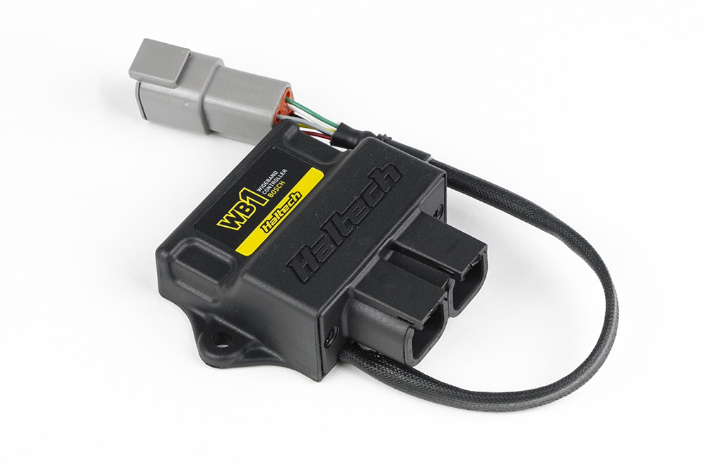

Much like the Bosch wideband, the NTK units come in a single channel and dual channel variation and will read reliably all the way down into the 2:1 air-fuel ratio range for methanol drag cars – that’s more than twice the range of the Bosch sensor.
Both the Bosch and NTK Wideband Controllers are auxiliary CAN devices which means they have their own control system and processor built into the control unit and transmit the air-fuel ratio data back to the ECU via a communications protocol known as CAN.
More useful information
In a reading mood? Check out our Tech Library full of useful info, tips and tutorials.
Short and Long Term Fuel Trim
One of the great things about tuning in volumetric efficiency mode is that once the fuel system is set up correctly the engine almost tunes itself – and that’s exactly what we are going to look at in this article.
If you’re not familiar with the concept of Volumetric Efficiency (VE), what it is, how it works, and the advantages of an EFI system that uses a VE model for fuel delivery we suggest you brush up on your knowledge here. If you want to jump straight to the point here is the condensed version:
VE Tuning Basics
When tuning an engine in VE mode the fuel map is actually mapping the amount of air going into the engine, the number that you see in the fuel map is typically between 50 and 100, this number represents how efficiently the engine fills with air at the particular load and rpm site in the map. So 80 in the VE map means the engine fills to 80% of its capacity at this load and RPM.
The ECU then uses this calculated airflow rate along with the injector flow rate and target air-fuel ratio to determine how long to open the fuel injector for.
If you have all the correct information in the ECU for injector flow rate, fuel type and engine capacity plus your MAP sensor and intake air temp sensor are working correctly when we measure the actual air-fuel ratio in the exhaust it should match the values we put into the target air to fuel ratio. If the actual and the target air-fuel don’t match – chances are the numbers you put into the VE map aren’t accurate for the particular load and RPM you are operating in.
So what do you do? You tune the VE map, or in other words, you modify the base fuel map, which is actually an airflow map. Increase the number for more fuel, decrease the number for less fuel. This is done in each cell of the map until your actual air-fuel ratio matches your target air-fuel ratio.
ECU, tune thyself
So if all we are really doing in tuning the VE map is adjusting the VE number up or down until our actual and target air-fuel ratios meet – can’t we just tell the ECU to do this automatically and learn this information. Like self-tuning?
The short answer to that question is yes. When you add a wideband O2 sensor to any Elite or NEXUS series ECU, the ECU can be set up to apply these fuel corrections automatically. Some people call this auto-tune, others call it self-learning, it’s all the same thing. In Haltech terminology, it’s called Long Term and Short Term Fuel Trim (LTFT and STFT).
Short Term Fuel Trim
To turn on O2 control in the Haltech NSP tuning software navigate to the “Fuel Tuning” section and turn on the “O2 Control” function checkbox. You can also navigate to all the tuning functions by pressing the F4 button and turn on O2 control from here.
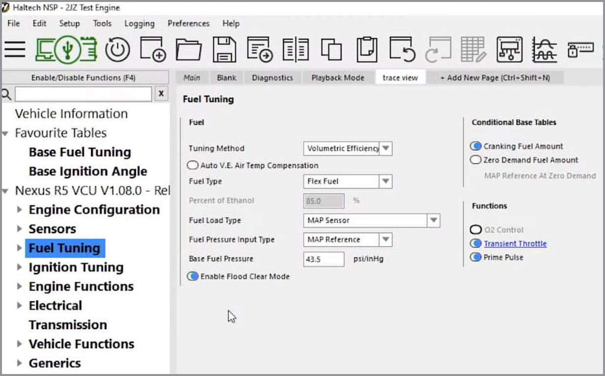
In the O2 Function Setup page, we have the control parameters that the O2 control is going to work under, most of these are easily understood. Things like Initial Engine Run Time, Minimum Coolant Temp, and Minimum and Maximum RPM settings don’t need any explanation.
We will concentrate on the 4 settings that we get the most questions. The dropdown box allows you to select which sensor you are going to use for O2 control. 9 times out of 10 this will be the only sensor you have so it’s a simple decision. However, there are times where you may have more than 1 O2 sensor in which case you would select the configuration of O2 sensor that matches your engine.
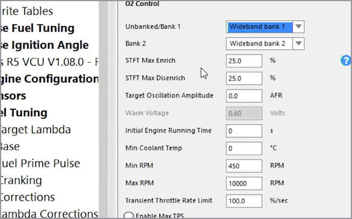
In our example, the engine is a straight-six, but since it’s got two exhaust manifolds and two 02 sensors we will assign a Wideband to each bank.
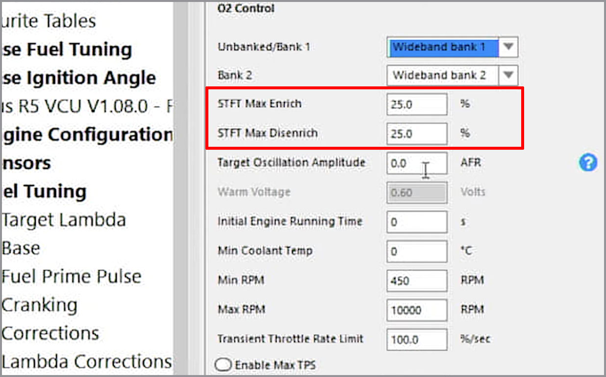
The next setting in the software is the “STFT Enrichment” and “STFT Disenrichment”. This is where we need to understand how the O2 control system works in a broad sense.
Short Term Fuel Trim can be thought of as an instantaneous adjustment because the O2 sensor looks at the actual air-fuel ratio, compares that to the target air-fuel ratio if they are different an immediate correction is made.
However this Short Term Fuel Trim is just that – short-term. It does not get stored or saved anywhere, so no ‘learning’ is ever applied. For the ECU to learn and save this information we need to go down to the Long Term Fuel Trim settings which we’ll get to shortly. First, we need to clarify the least understood setting in the Short Term Fuel Trim function and that is the Target Oscillation Amplitude.
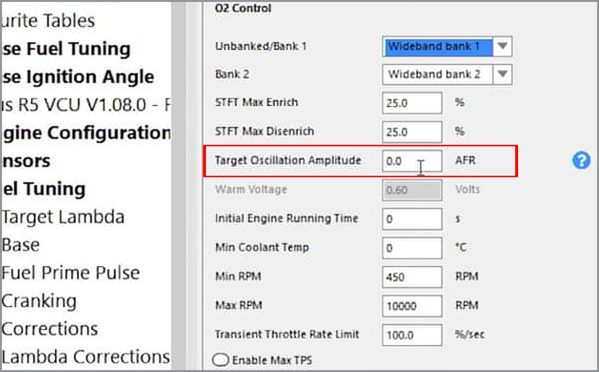
The default setting here is 0.0, which means if the ECU is targeting a 14.7:1 air-fuel ratio then the O2 control system tries to maintain a steady 14.7:1. If we were to put say 1 air-fuel ratio point in here and the target air-fuel ratio was 14.7:1, the O2 control would try and oscillate the actual air-fuel ratio between 13.7 to 15.7.
Why would you want the air-fuel ratio to bounce around for this? To control your emissions. In order to achieve near-zero tailpipe emissions, we must use a catalytic converter. A catalytic converter works like a sponge in that it continuously fills up and empties so it needs a continuous, oscillating mixture of slightly lean then slightly rich mixture. That oscillation amplitude is what this setting is for. If you are not familiar with tuning an engine to achieve a high level of emissions reductions we recommend leaving this value at 0.
Long Term Fuel Trim
For the ECU to actually learn or save any information about the required fuel trims we have to turn on the Long Term Fuel Trim (LTFT).
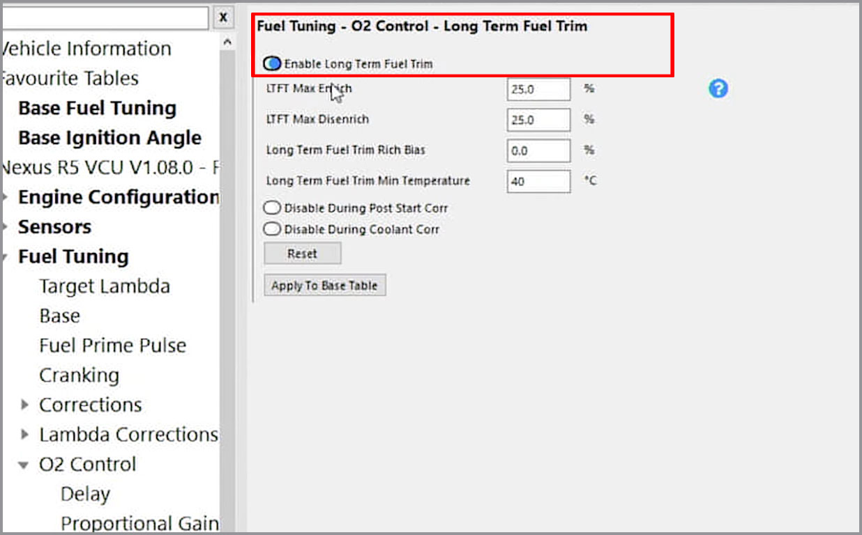
We have some similar settings here, LTFT Minimum and Maximum Values, a Minimum Temperature under which the ECU won’t learn any O2 control and there is also this “Long Term Fuel Trim Rich Bias” value.
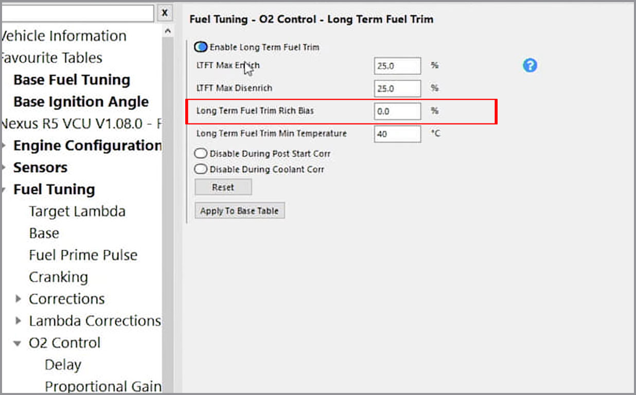
Think of this as a safety factor. The long-term 02 control will target and learn according to what values are in the target air-fuel ratio map. However if you put a value of say 3% in the “Rich Bias” setting, the O2 control learns to a value 3% rich of the target and then relies on the Short Term Fuel Trim to remove that extra 3%. The reasoning behind this is if the O2 sensor becomes unplugged or fails for any reason, the ECU has learned 3% on the safe side.
There are a couple of other control parameters that are worth mentioning; the first one is the Long Term Fuel Trim Gain map – this map sets the speed at which the O2 control converts the instantaneous short term trim into a long term learned value – the bigger the number the faster the learning.

The theory here is as engine speed and engine load increase there is enough reliable data to write to the long-term learned value as quickly as possible. At lower engine speeds and lower engine loads, you may end up chasing your tail if you write to the long-term trim too quickly so you slow down the writing to long-term and allow the short-term instantaneous correction to do the bulk of the work. This is why you see smaller gain values in the low RPM areas of this map.
Want to know more?
Where is the Target AFR value is coming from? The ECU gets that information from the “Target Lambda” map but we don’t target the same lambda or AFR value for each load and RPM. If you want to know why – watch our AFR vs Ignition Timing video.
Ignition Timing VS Air to Fuel Ratio
In this article, we are going to shed some light on the hotly discussed topic of how and why the air-fuel ratio and ignition timing affect horsepower.
And this is how we’re going to do it…
First, we are going to need some hard data. Using our test vehicle, we are going to do three power runs on our chassis dyno. In those three power runs, we are going to alter nothing except the target air to fuel ratio.

With that data up on the dyno screen, we are going to analyze the difference in performance from changing nothing more than the volume of fuel that is being delivered to the engine.
We will then do another set of three dyno runs, but this time keeping the air to fuel ratio consistent and vary the ignition timing by 2 degrees.
Air-Fuel Ratio and Horsepower
Here we have 3 dyno runs, back to back with no changes to anything except the air to fuel ratio.

Note how underwhelming the power gains are. Three completely different air-fuel ratios yielded almost identical power.

So why the big fuss with air-fuel ratio if they all make the same power and more practically – what air-fuel ratio should you be targeting for your engine? To understand this we need to dig a bit deeper into the relationship between the air-fuel ratio and horsepower.
It’s all relative
What we see on the dyno graphs seems a bit counter-intuitive since the power output is only very loosely related to how much fuel we put into the engine. We can safely assume there is a fairly wide range of air to fuel ratios that we can run this engine at and make exactly the same power.
Sure if we go too far out on the rich side we will start to lose power. We’d probably also start to foul the spark plugs and put fuel into the oil as well.
We’ll get similar results when we start to lean out the engine. We’ll start losing power, though rather than fouling the spark plugs and diluting the engine oil, we will eventually melt pistons and cause catastrophic engine failures.
NOTE: On a turbocharged engine like the one in our test car, we could start leaning the engine out under full power to a point where we risk damaging it before we see any drop in horsepower. Take our word for it and don’t try it at home!
Meanwhile, inside your engine…
Just before we set off the spark plug, we have a mixture of air and fuel that are about to combine in a chemical reaction we call “combustion”.
Combustion produces heat. Heated air expands, but in our combustion chamber, there is no way for the air to expand to except down. Why down? There is only one movable thing inside the combustion chamber and that’s the piston. As the chemical reaction of combustion takes place, more and more heat is generated as we combine more and more of the air with the fuel inside the cylinder.

Eventually, we create enough pressure to push the piston down the bore. From here, the piston’s connected to the rod, the rod’s connected to the crank, the crank’s connected to… the burnouts!
The chemistry of combustion
Let’s take a closer look at the process of combustion. Like in any chemical reaction there is a specific ratio of the components that ensures we get a complete reaction. An excess of any one of the components just doesn’t get used.
In the case of our engine, the two components needed to complete our chemical reaction are air and fuel. One of those two components however is limited – the air. Why? There is only so much air we can stuff into our engine (if you haven’t read our article on Volumetric Efficiency do so now, because Volumetric Efficiency is all about how much air can be stuffed into an engine).
So we have a fixed amount of air available for our combustion reaction and we use the ECU to calculate the amount of fuel we need to put into the engine to match that incoming air.
Stoichiometric AFR
If we go back to the chemistry for gasoline the ideal amount of fuel we should be delivering to the engine for a complete chemical reaction is roughly 14.7 parts air to 1 part fuel by mass. We call this the Stoichiometric Air to Fuel Ratio. If we provide the engine with exactly 14.7 parts air to 1 part fuel all of both the air and the fuel get used up completely in the chemical reaction of combustion.
Of course, we know from experience that if we do this at 15 pounds of boost and 8000 RPM we stand a good chance of blowing the engine into oblivion and eating the pistons for lunch. However, if we just throw in a bit more fuel and run it at 12.5 parts air to 1 part fuel, the engine will happily run for hundreds of thousands of miles, making exactly the same horsepower.
Here is the curious thing though; in both cases, the engine is making the same horsepower, so it must be generating the same amount of heat, so why would one AFR result in melted internals and the other not?
Feeling the heat
It all comes down to that extra fuel. That additional fuel that we added actually cooled the combustion chamber from the inside preventing the excess heat build-up that causes the pistons to melt when the engine runs too lean.
When we say “too lean: we don’t mean “lean of the Stoichiometric 14.7 value”, we are talking about lean of the point where you cause engine damage, which on a turbo or supercharged engine is well before 14.7:1. So we can conclude that horsepower is generated by producing heat but – the more heat you produce, the more fuel you need to add in order to cool the combustion chamber.
This is exactly why if you look at the target air-fuel ratio map in your software, the target gets richer with RPM and richer with manifold pressure.
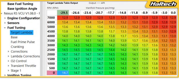
It gets richer with RPM because you are producing the heat more often. It gets richer with manifold pressure because manifold pressure represents how much air is going into the engine.
I can see clearly now
Let’s go back to the dyno graphs. All three runs have different air-fuel ratios but are all making the same power. This now makes sense, because we know we put the same amount of air in each of these runs so we could only ever hope to produce this amount of power from the combustion reaction.
The only difference in these runs would be in the engine’s internal combustion chamber temperatures. If we were able to measure these we would find that the temperature inside the chamber went down to a point where we reduced the combustion chamber temperature so much, we actually lost power. The trick here is knowing which of these air-fuel ratios delivers the best balance of engine longevity, fuel economy, and maintenance intervals.
NOTE: On a turbo engine like the one in our test car you should err on the side of caution and under full power the engine should be at the richest air-fuel ratio possible, whilst still maintaining peak performance. This would be transitioned to leaner mixtures as the engine load and RPM decreased.
Ignition Timing and Horsepower
For the second part of our demonstration we will run the car a couple more times, but this time we won’t touch the air-fuel ratio – instead, we will change the ignition timing.

The dyno graph clearly shows that just 2 degrees of timing shift cause significant changes to the output power. The difference between the two runs here was 20kW. while keeping the same air-fuel ratio and the same boost.
How does that happen? If there is no more or less heat being generated and we have the same amount of air and fuel in the reaction why are we making more power? To understand this we need to shift from chemistry to physics.
Let’s get physical
The engine’s rotating assembly is called just that because all its parts are moving. Rotating to be exact. This is important because if we apply the same amount of pressure to the crankshaft when it’s further around its rotation we get more leverage with the same force.

It’s important to note here that combustion doesn’t happen instantly. Once we light the fire at the spark plug, the fire spreads over a period of time. During that timeframe, the crankshaft is rotating and the piston is moving down. We need to allow for that delay when setting our ignition timing.

This is why as RPM increases we have to start the fire earlier and earlier (ie put more advance in the ignition timing map) giving the fire enough time to spread and create peak cylinder pressure at that same angle after TDC that creates maximum mechanical advantage on the crank.
There are so many competing factors going on with the ignition timing there really isn’t a reliable way to map your ignition timing correctly without using a dyno. You need to be able to actually receive real-time feedback on whether starting the spark earlier or later produced more or less mechanical advantage in a dynamic environment.
But the dyno graphs clearly show that with the same amount of air and the same amount of fuel (therefore generating the same amount of heat) we were able to get more power by simply moving the spark event to a time where it gained more mechanical advantage.
The verdict
The question on all the internet forums is “which is more important – ignition timing or AFR?” and just looking at the dyno graphs from our two experiments you could be forgiven for thinking the ignition timing has it. But if you’ve watched the video and read this article in full you’ll understand that it’s a bit more complicated than that.
The truth is – they are both equally important because they serve different purposes. The air-to-fuel ratio is used for thermal management, it’s there to ensure the engine produces just the right amount of heat to operate. The ignition timing is used to optimize the mechanical advantage within the engine’s cycle to produce power more efficiently.
Tuning with VE (Volumetric Efficiency)
Volumetric Efficiency or VE is a measure of the actual amount of air that is moved through an engine vs the engine’s cubic capacity.
Your engine is an air pump
You may have heard the saying that “an engine is just an air pump”, what that means is if we just forget for a moment about the process of combustion that happens when the valves are closed, for every engine cycle all we are really doing is taking air from the intake manifold – sucking it into the combustion chamber – and them pumping it out into the exhaust manifold. Or simply, pumping air from intake to exhaust – thus the description of an engine as an air pump.
If we think of our engine as an air pump, we know that for every engine cycle our pump should suck in and pump out a fixed volume of air. The volume of air our engine pumps should be equal to the engine’s cubic capacity, so a 350 cubic inch engine should move 350 cubic inches or 5.7 litres of air.
However, if we were to put a flow meter on the front of our air pump engine and actually measure the amount of air that was being pumped we would find it doesn’t always equal the engine’s capacity. It’s normally a little bit lower – that’s because our engine is not 100% efficient at moving air from the intake to the exhaust. If it was, we would say the engine has 100% Volumetric Efficiency.
Much of the work in engine design and engine building is focused on improving this volumetric efficiency. Things like intake runners, exhaust headers, valves, and camshafts all play a big part in how efficient our engine air pump is at moving air from the intake to the exhaust.
So that’s what Volumetric Efficiency is: a measure of the actual amount of air that moves through an engine vs its cubic capacity.
Why is VE important for tuning engines
Volumetric Efficiency tells us how much air is going into the engine and knowing how much air is going into the engine is essential for figuring out how much fuel to deliver to the engine. The right mix of air and fuel (air to fuel ratio) is critically important to not just making good horsepower, but also in ensuring an engine runs reliably and predictably for many miles.
We have already established that engine design considerations like intake runners, exhaust headers, valves, and camshafts all affect VE, but once the engine is together, they are all relatively locked in and fixed and once the engine is up and running the biggest factors that affect how efficiently our engine can pump air are engine load and engine speed.
Knowing that we can now see that volumetric efficiency is important to an engine tuner because it tells us how much air is going into the engine and we can use that information to determine how much fuel to deliver.
Measuring Volumetric Efficiency
Nothing you’re about to read in the following paragraphs invalidates the previously stated definition of volumetric efficiency, but for the sake of better understanding, it’s worth delving a bit deeper into it because, technically, it’s a really poor definition. Why? Because we don’t actually measure the volume of air (or anything else) that goes through an engine.
Confused? Keep reading and it’ll all become clear. Volume is a measure of 3-dimensional space, measured in cubic centimeters or cubic inches. Air is a gas (or rather a mixture of gasses) and you can’t measure gas as a volume. It’s a bit like saying I am going to measure the weight of my car in dollars – it makes no sense, they are different things, one is weight the other a currency.
However, if we said cars are worth $1 a pound and my car weighs 1000 pounds, I’ve got a $1000 dollar car. That equation works just fine.
That’s similar to what we actually do with volumetric efficiency – we have a known volume of the engine and we want to calculate the mass or weight of the air that passes through the engine in one engine cycle and compare that to the mass of air that would reside in the engine’s total volume.
So perhaps a better decscription for Volumetric Efficiency wouble be: the actual mass of the air that passes through our engine in one engine cycle vs the mass of air that would be found in the cubic capacity of that engine.
But that’s all a bit wordy and possibly confusing and definitions should be short and to the point, so let’s can stick with the earlier definition.
What affects VE?
What we are most interested in is the mass of the air, and that’s because mass is affected by temperature and pressure. This isn’t really a problem, we can control this – we measure both air temperature with the intake air temperature sensor and air pressure with the MAP sensor. So running 15 or 30 or 60 psi of boost does not double, triple or quadruple our engine efficiency. How could it?
Our air pump didn’t get more efficient at pumping air from intake to exhaust just by adding air into the intake at a higher pressure. No, our air pump is equally efficient under boost, we simply make more power because of the higher air mass in the same air volume, but we are no more efficient at moving it from one point to another.
But wait, earlier on we stated that VE varies with RPM and Engine Load, and the fuel map axis are based on these two variables precisely because they change the VE. Isn’t this directly contradicting it? While on the surface it may sound contradictory it actually isn’t. That’s because boost alone does not change VE. To understand that let’s take a look at where that boost comes from.
Most of the time, we are getting boost from a turbocharger, and what is a turbocharger if not just another air pump, an air pump with its own set of efficiencies on both the intake side and the exhaust side. This turbo air pump directly affects the engine air pump efficiency because it’s restricting both the intake and the exhaust side of the engine air pump.
It’s worth noting here that this is not the case for superchargers. While they too are effectively air pumps with their own efficiency, they do not affect the engine air pump efficiency and therefore have no effects on engine VE. Another big restriction, the one we intentionally put in place and whose sole purpose is to reduce engine efficiency, is the throttle.
Fuel Map Axes and VE
Once the engine is bolted together VE will vary with RPM and engine load, but since the engine load is controlled by the throttle we could – and often do – use the Throttle Position as one of the axes in the VE table instead of the Manifold Pressure.
Most people will be more familiar with using Manifold Pressure as the load axis of the VE table which is fine because the only way to get into the vacuum areas of the VE map is to close the throttle and so manifold pressure correlates pretty consistently with throttle position in the vacuum areas.
On the positive pressure side of things, because a turbo acts as a restriction on both the intake and the exhaust side of our engine pump, and both the compressor and turbine wheels have their own separate efficiency curves so it’s not uncommon to see changes in engine VE with a change in boost due to the turbocharger efficiency’s effect on engine VE. Therefore it’s perfectly acceptable to be using either Manifold Pressure or Throttle Position as the load axis along with RPM when tuning the engine’s VE map.
Then of course there are things like variable cam timing, the cooling effect of methanol on the incoming air charge, wastegate opening and exhaust back pressure and intake bleed valves and nitrous injections but we won’t be covering these topics in this article. The underlying principles of tuning all VE-based systems are the same.
VE and your ECU
The ECU needs to know a few basic parameters to do its job:
• The engine volume
• Manifold Pressure
• Intake Air Temperature
The ECU is going to use that information to calculate how long to open the fuel injectors. To do that effectively the ECU will also require some information about the fuel system:
• Injector Flow Rate
• Injector Dead Time
Now that the ECU is reading the actual intake air temperature from the air temp sensor and the air pressure from the manifold pressure sensor, it can calculate the mass of air that should be entering the engine based on the engine capacity.
The ECU then looks in the base fuel map or VE map to find out how efficiently the engine pumps air from intake to exhaust at any given RPM and load. With this information, an accurate calculation of the actual mass of air passing through the engine at any point in time can be made.
Of course knowing the mass of air going through the engine isn’t the end goal here – delivering fuel to the engine is, so knowing the mass of air going through the engine the ECU looks over to the target air fuel ratio map to determine the mass of fuel it needs to deliver.
NOTE: When we say we want an air to fuel ratio of say 14:1, we are actually talking about the relative mass of air going through the engine to the relative mass of fuel going through the engine. So 14:1 means for every 14 kilograms of air that passes through the air we need to deliver 1 kilogram of fuel.
Different fuels have different densities and stoichiometric air-fuel ratios and all VE-based systems will have a setting to let the ECU know the density of fuel you are using and somewhere to set or select the stoichiometric air-fuel ratio of your fuel.
Now the ECU has enough information to both determine the mass of air entering the engine and calculate the mass of fuel it needs to deliver out of the fuel injectors to give you that air-fuel ratio that you are targeting in the target air-fuel ratio map.
It’s business time!
We can now measure to see if all that math worked. We do that with a Wideband O2 sensor in the exhaust. This sensor tells us what the actual mass of burned fuel is relative to the actual mass of air. We take this reading of actual combusted air fuel ratio and compare it to our target air fuel ratio map and if the actual AFR does not match up to our target, one of our settings is wrong.
It could be any of the settings mentioned ealier; you have entered an incorrect flow rate for the injectors, you have told the ECU an incorrect engine capacity, your MAP sensor or air temp sensor are reading incorrectly. All these can be easily checked and fixed. It’s most likely that the VE number entered into the base fuel map is not actually the correct volumetric efficiency for your particular engine.
We are at a point now, where we move on to the actual process of tuning or calibrating the fuel map. Which, when you boil it all down, is just the process of adjusting each of the cells in the VE map until the actual air-fuel ratio that we read from the O2 sensor matches the target in the target air-fuel ratio map.
Fast Facts
• Volumetric Efficiency or VE is a measure of the actual amount of air that is moved through an engine vs the engine’s cubic capacity.
• The engine’s Volumetric Efficiency map is used in an engine control unit to calibrate how much fuel to deliver to the engine.
• It’s important to ensure that you enter the correct engine capacity, injector flow rate, and target air-fuel ratio if you want the system to respond how you would expect it to.
EGT sensors – everything you need to know (and then some)
EGT stands for Exhaust Gas Temperature, and to measure it we use EGT sensors. The most common EGT sensor is a K-type thermocouple, but not all K-type thermocouples are used to measure the exhaust gas temperatures.
You see we could also use K-type thermocouples to measure air temperatures, coolant temperatures, oil temperatures or anything else you can access to and install a K-type thermocouple on.
What is a Thermocouple
A thermocouple is a temperature sensor made up of two dissimilar metals. At different temperatures the dissimilar metals react to each other differently and produce a tiny amount of voltage.
We can put that voltage through an amplifier and, as long as we know the metals we are working with, we can come up with a temperature calibration chart, thus calculating what temperature the sensor is measuring.
There are several different EGT material types that are known by their lettering: J, K, T, N, E, B, R, S and more. Each letter assignment has different working temperature ranges, is made of different materials, has different acceptable error ranges and different life expectancies.
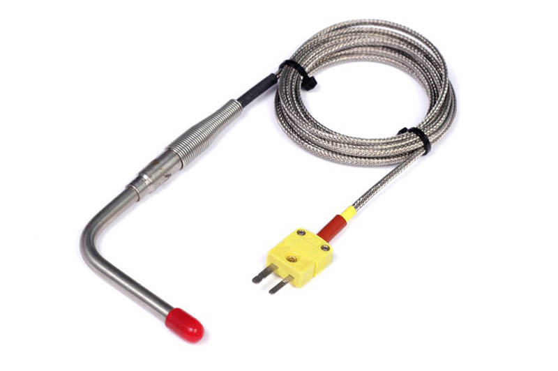
The most common Thermocouple type in our Automotive world is the K Type. The K Type Thermocouple is made up of Nickel-Chromium and Nickel-Alumel, which gives this sensor an operating range of -200 Celsius to 1260 Celsius. They are inexpensive, reliable, highly accurate and have that wide temperature range.
The Haltech brand K-type sensors come terminated into the 2 pin connector known as a Mini-K type connector. You can specify the cable lengths you need which makes fitting sensors easy – simply plug them straight into the required thermocouple amplifier.If you are terminating your own K-type thermocouple sensors into the amplifier make sure to get the wiring around the right way – its important.
The yellow wire is the Positive signal and is the pin made of Chromium. The Red wire is the Negative signal and is the pin made of Alumel. If you open the Mini K-type connector there will be a + and – symbol there to help identify which pin is which.
Shapes and sizes
The sensors come in a range of different physical appearances and shapes.
The sensors used to measure exhaust gas temperatures are typically 1/4inch open tip, but you can also get 1/8 inch open or closed tip sensors. The sensor you choose would depend on your application, but typically the ¼ inch open tip is the most common for EGTs.
The difference between an Open or Closed tip is in the response time and reliability. An Open tip sensor will react to a temperature change in around 200ms, while a closed tip sensor will react in around 800ms – a bit slow if you are looking for rapid changes like an ignition misfire.
You can also get K-type thermocouple that look like a washer, these are perfect for fitting under a bolt head to measure surface temperatures. A 1/8 closed tip sensor would be perfect for measuring fluid temperatures because you wouldn’t want to submerge an open tip sensor for too long.
Where and how deep?
It’s important that all your EGT sensors are installed at the same distance from the cylinder head and at equal depths. The depth will depend on the type of induction you’re running – in naturally aspirated engines the probe needs to sit in the centre of the pipe while in engines with forced induction the probe will be no more than 6mm into the pipe, so much shallower than in N/A engines.
Amp it up!
The K-type thermocouple requires an external amplifier to get the data into the ECU. This is due to the fact that the thermocouple itself only outputs a voltage of around 60mv across its almost 1500c working range. The amplifier is there to convert this tiny voltage into data we can use in the ECU. The Thermocouple Amplifier (TCA) integrates with the engine management system via the CAN communication system.
It’s amazing to think these sensors have a working range of 1500 degrees Celsius, given they are basically just made up of two dissimilar metals bonded together to make a tiny voltage, which is then amplified for the ECU to see and they do it while maintaining a maximum error of just 2.2 degrees Celsius which is less than 1%!
Setting it up
Once you have the thermocouple probes installed and connected to your TCA (Thermocouple Amplifier) it’s just a simple matter of connecting the TCA to your Haltech ECU and setting the EGTs up in the Haltech software.
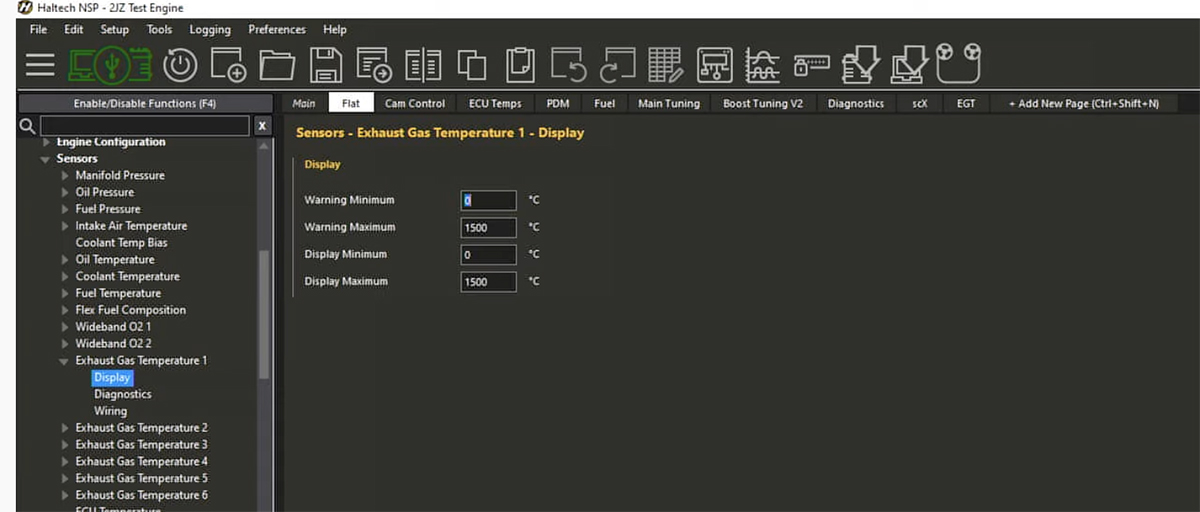
You will find the EGTs under “Sensors”. In the “Display” menu you will need to set up your minimum and maximum display temperatures as well as minimum and maximum warning temps. These temperatures determine a range at which your ECU will log the EGTs.
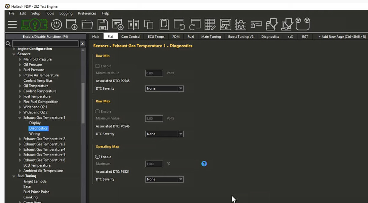
The “Diagnostic” menu lets you keep an eye on each individual EGT sensor and identify any potential problems like voltage/temperature spikes or drops which will then can trigger an error code.
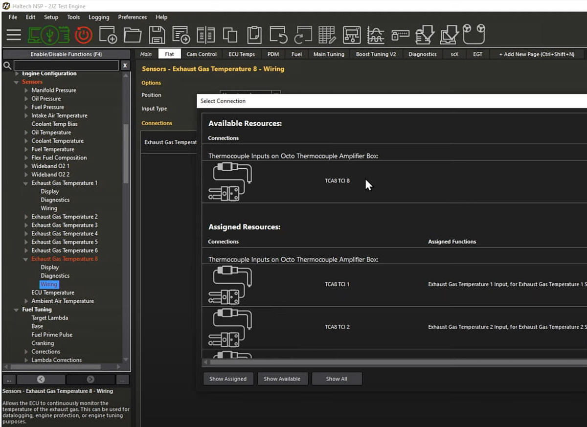
All your connections are set up in the “Wiring” menu. This is where you connect your EGT sensor to an available channel and define the sensor type.
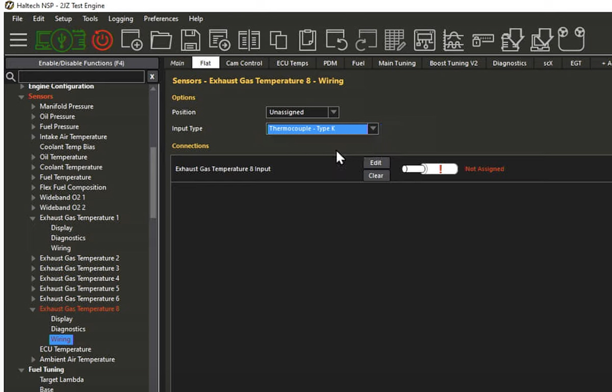
In this case we’re using a Haltech K-type thermocouple which is chosen through a drop-down menu. If you’re using Haltech’s K-type sensors, you don’t need to calibrate them, all the information is already set for you in the software.
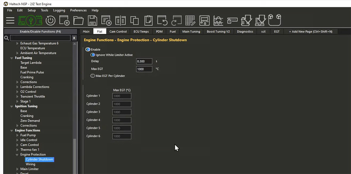
We can also use EGTs to trigger an individual cylinder shut down. Scroll down to “Engine Protection” and set your shut-down parameters for each cylinder in the “Cylinder Shutdown” menu.
And that’s about it. Remember, if you have any questions or need a hand setting up your Haltech ECU we are always happy to help – contact us on [email protected].
How to switch between tunes with a dash switch
Want one map for the track and one for the street? Want to change the characteristics of your rev limiter as you are driving? How about being able to choose from as many as 12 different target boost levels? All this and more is possible with the Haltech rotary trim module!
Basics first
Let’s say we want to have a few different boost curves programmed into the ECU for different scenarios. For example a softer curve for a wet track, a more aggressive curve for good track conditions and something in between for day to day driving.

We then want to be able to switch between these curves without having to plug a laptop in. To do this we need to have a way to tell the ECU which boost level we want at any given time, and that’s where the rotary position trim module comes in.
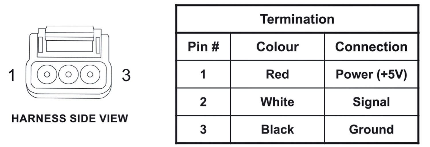
The rotary trim module has 3 wires; power, ground and signal. When you change the position of the knob the module sends a voltage down the signal wire to the ECU.

Different positions on the knob send different voltages to the ECU and the ECU uses this voltage information to change how it behaves.
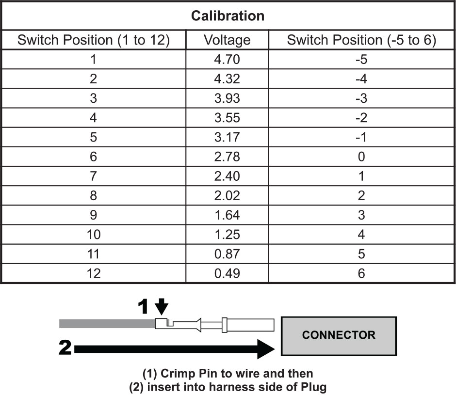
With the module wired in we can now program the ECU to target say 15 PSI of boost on position 1, and 22psi on position 2, and so on.
Setting it all up
Using ESP software for Elite Series ECUs go into the Setup menu, Main Setup, Functions, and select “Rotary Trim Module 1”. Currently, you can have up to 3 modules controlling any number of different functions at once.

Hit the Edit Connection link and select an available input to wire the signal wire to. There is also a calibration tab which has been preconfigured to match up with the voltage output of the Haltech 12 position trim modules.
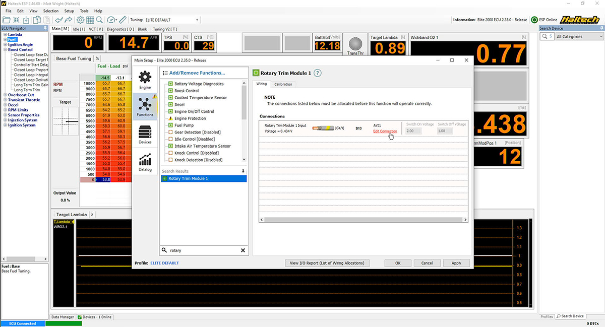
With the input setup sorted let’s head into the tuning maps. Starting with boost, we navigate to the Boost Control and within the Boost Control Map we select Setup, Table Setup or simply press the F3 shortcut key.
We are now in the Axis Setup for Boost Control. Originally this was set up for RPM but now we want to add another axis to that map. Select the Axis to be “Rotary Trim Position Knob 1”. Let’s add a few positions in here and press OK.
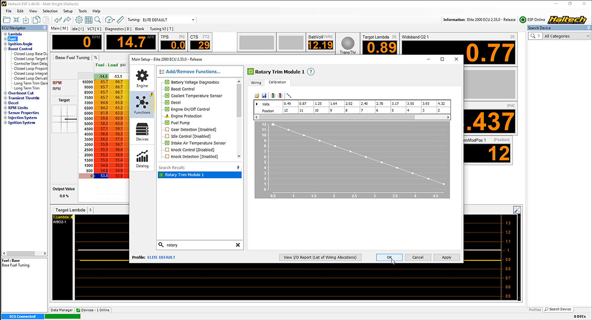
Now when we go to the Target Boost Map, we have 5 different target boost levels based on the position of the trim knob. We can now change the numbers to go from full send boost all the way down to grocery getter at the twist of a knob.
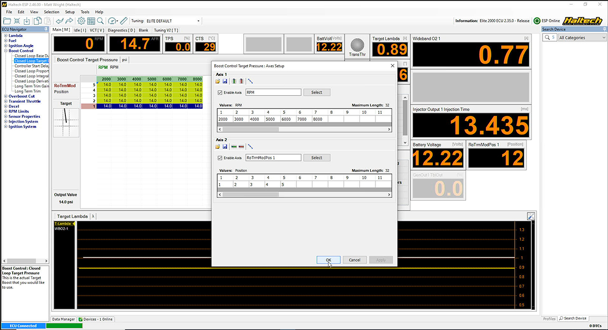
But wait, there’s more!
The trim module is not restricted to just boost control. You can use the same knob to also control any other function in the ECU.
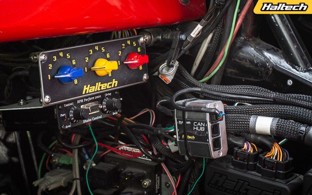
Along with a 10psi target boost level at position 2, you might also want to drop the rev limit down to a measly 4500 RPM. This is a common setting for a “valet mode” or for those times when you hand over the keys to your significant other.
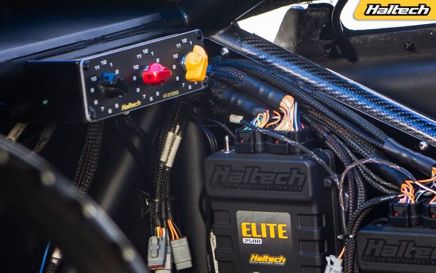
You can also adjust the ignition timing or lean the fuel out a little for that extra economy – the process is the same. Go to the map you want to make changes on the fly with, add the trim knob to an axis of that map and make your changes based on the position of the knob.
NOTE: if it’s fuel that you want to trim out or add in, the place to do this is in the Target Air Fuel Ratio map and not the main VE map. This way, when you add your new map axis to one of the target AFR maps the ECU will “learn” toward the updated target. If you make corrections to the main VE map, however, the ECU will just learn its way back to whatever is in the target AFR map.
You can get as creative as you like with these rotary trim modules they really do put all the ECU functions at your fingertips, so don’t be afraid to experiment.
If you have further questions contact us on [email protected]
Rotor Phasing Secrets
Even though modern engines don’t rely on distributors anymore, there are still plenty of race and historic engines that do.
What is a distributor?
Before individual coil on plug ignition systems, engines used to have a single coil and a mechanically driven distributor which would accept the spark from the coil then distribute said spark through the rotor button, through the distributor cap, through the spark plug leads, and finally to the spark plugs.
At the time it was a really clever way of doing things, way before engine management systems had the ability to fire a coil per cylinder.

How does a distributor work?
A distributor is driven off the camshaft and runs at cam speed which, in a 4 stroke engine, runs at half the speed of the crankshaft. As the distributor shaft turns;, the “Rotor Button” (which is connected to the top of the shaft) spins and directs the incoming spark (which it receives through a spring-loaded pin on the inside of the cap) to the correct cylinder.
In order for the coil to generate a spark, it needs a charge signal synchronized with the engine position and speed. This is produced by a set of “Points” which are driven off lobes on the distributor shaft, an electronic ignition system which is triggered from a reluctor sensor on the distributor shaft, or from an engine management system which is being triggered off a crank and/or cam sensor.
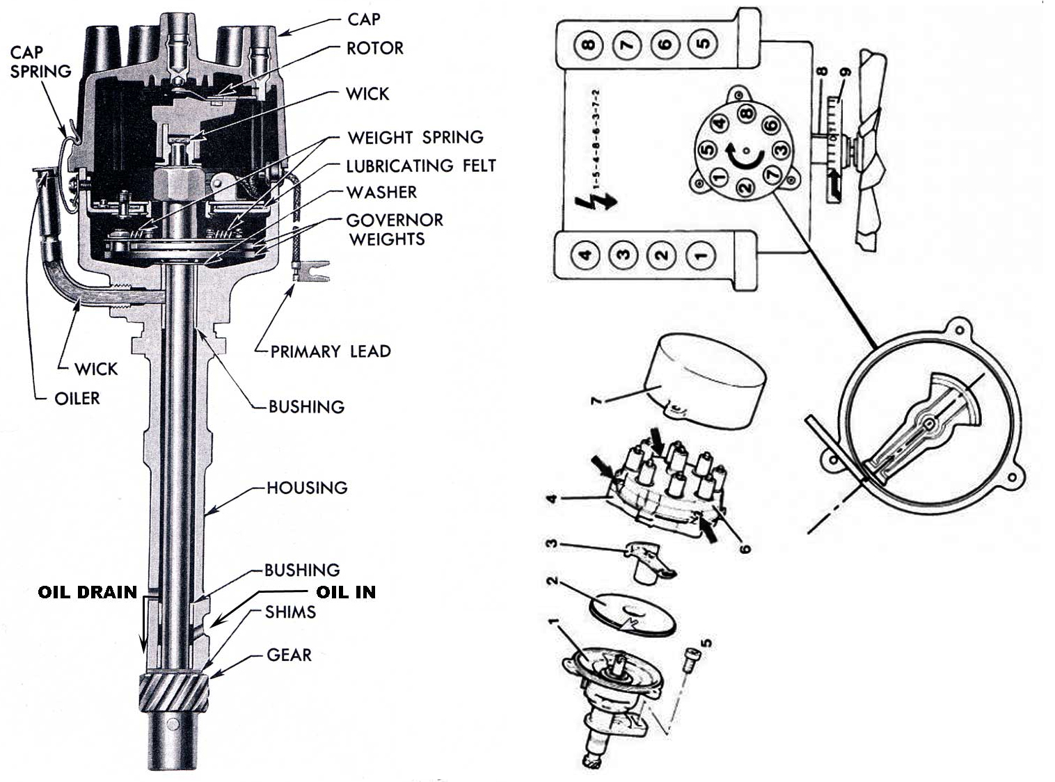

What is Rotor Phasing
Common engines like the small block Chevy, Ford Windsor or the mighty Datsun L-series all relied on a distributor to take care of their ignition duties so Rotor Phasing is not a new thing, it’s always been there, it’s just that we didn’t always have infinite control over our ignition timing to amplify potential problems.
In factory form, you would twist the distributor to advance or retard the ignition timing, which would affect the full operating range of the engine, but it’s not so much the position of the rotor cap, rather the position of the points or electronic ignition inside the distributor which is in control of when the coil fires. So when you twist the distributor you’re moving the triggering event and the rotor phasing at the same time, inadvertently avoiding the problem that we are talking about.
Things get a little more complicated when we add a modern engine management system triggered from a crank position sensor which then sends a signal to the coil to fire through the distributor to the desired spark plug.
When we change the desired ignition timing in the ignition mapping we aren’t physically twisting the distributor to get the result. Instead, we are firing into a locked distributor and therefore need to make sure that the spark can mechanically make its way through the rotor button to the right cylinder – and that’s what’s known as rotor phasing.
How Rotor Phasing works
In order to produce the highest spark energy possible and reduce the risk of cross-firing we need to get the rotor button as close as possible to the post for the desired cylinder when the spark fires.
If the engine comes around to 30 degrees before top dead centre cylinder 1 and the rotor button is sitting right over the top of the post for cylinder 1 when the coil fires we’ll get a good firing event, but if the button is sitting In between cylinders 1 and 3, or sitting over here on a completely different cylinder we will get a cough, a bang or a backfire and the engine won’t run.
This isn’t something the engine management system has any control over so we need to physically install the distributor in the correct position relative to the desired firing angle.
Rotor Phasing and Continuously Variable Ignition Timing
In the first example we had the rotor button sitting over the post for cylinder 1 when the engine was at 30 degrees before top dead centre, but engines can run with ignition timing ranging from, let’s say 20 to 40 degrees. If we fire the ignition timing at 40 degrees that means it’ll be sparking on the leading edge of the rotor button, whereas if we fire at 20 degrees it’ll be firing on the trailing edge of the button.
Don’t Do This!
The most common mistake when setting up rotor phasing is dropping the distributor into the engine with the rotor button lined up with cylinder 1 when the engine is at the top dead centre compression cylinder 1. This would only allow an ignition timing value of 20 degrees BTDC to 20 ATDC (or negative 20 to positive 20 degrees of ignition timing).
Any ignition timing value outside of these would result in misfiring or cross firing.
This is a common mistake because a lot of engines only have a TDC mark on the crankshaft, so it’s assumed you put the engine on TDC and line the distributor up with cylinder 1, but, as we’ve explained before, that is not the case.
Do This Instead:
We must insert the distributor with the rotor button facing cylinder 1 when the engine is positioned in the middle of the desired ignition range. In our example we are using 30 degrees as the middle of the working ignition timing range which is a good starting point for just about all distributed engines. If your engine only has a TDC mark you’ll need a way to position the crankshaft at 30 degrees before top dead centre cylinder 1.
The easiest way to do this would be to ask your engine builder to mark it when they have the degree wheel out for setting up the cam timing. If your engine is already in the car – don’t worry, there are other ways of finding your 30 degree marker.
You can buy a timing tape, which is an adhesive tape with all the angles marked on it. You simply stick it on the harmonic balancer and reference off that. Make sure to measure the diameter of your harmonic balancer and buy the correctly sized timing tape as the distance between the markings changes with the diameter of the balancer.
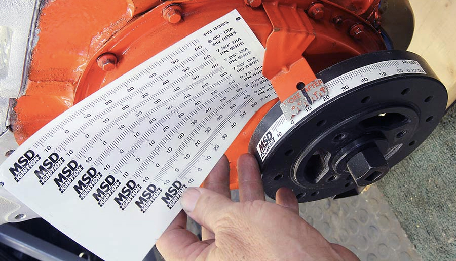
Alternatively, you could calculate the angle from TDC to 30 degrees using the following steps and a bit of high school maths:
1. Measure the diameter of your balancer, multiply that by pi (3.141592) to calculate your circumference.
2. Take your desired angle (30 BTDC) and divide that angle by 360.
3. Multiply that by the circumference you calculated in Step 1.
4. This value is the distance in length (metric and imperial measurements both work here), cut a piece of string to this length.
5. Tape one end of the string to your 0 degree (Top Dead Centre) mark. Then stretch the string around the circumference (the outer edge ) of your balancer, marking with a paint pen where it ends.
6. And that’s it, you’ve now got a 30 before top dead centre mark.
Getting into the swing of things
Let’s take a look inside a V8 distributor cap. We can see 8 terminals equally spaced inside the 360-degree circle, that means we have a terminal every 45 degrees. 360 divided by 8 equals 45.
If we’ve got a timing map that goes between 20 and 40 crank degrees or 10 to 20 cam degrees (remembering that the cam spins at half the speed of the crank), that means the spark will have a “swing” of 10 cam degrees and fire up to 10 degrees either side of the post and will give good results.
The swing is calculated by subtracting the highest ignition advance from the lowest ignition advance, then dividing by two to get the centre (so 40 minus 20 gives us 20 and 20 divided by 2 give us 10).
The name of the game is to have the smallest distance between the rotor button and the target post under all firing angles. It can help to source a rotor button with a wide firing surface, or a distributor with a huge cap and button effectively giving more distance between the posts and making cross firing less likely.
Some aftermarket manufacturers have tackled this issue by making the rotor button adjustable independent of the body of the distributor, this can help in custom applications where there isn’t enough adjustment in the distributor body to get the right phasing.
Let’s get real
So that’s the theory. Let’s put it into practice by using a real life example. We begin by looking at our desired ignition timing values, our example – 20 degrees minimum and 40 degrees maximum. 40 minus 20 equals 20 crank degrees of possible ignition timing change. That means 30 crank degrees is the middle of the working range (40+20=60. 60:2=30).
We want to install the distributor in the engine so the rotor button is facing Cylinder 1 when the crankshaft is at 30 degrees before top dead centre Cylinder 1. To do this, we mark the distributor body and shaft against the cap so that we know the correct alignment when we install it.
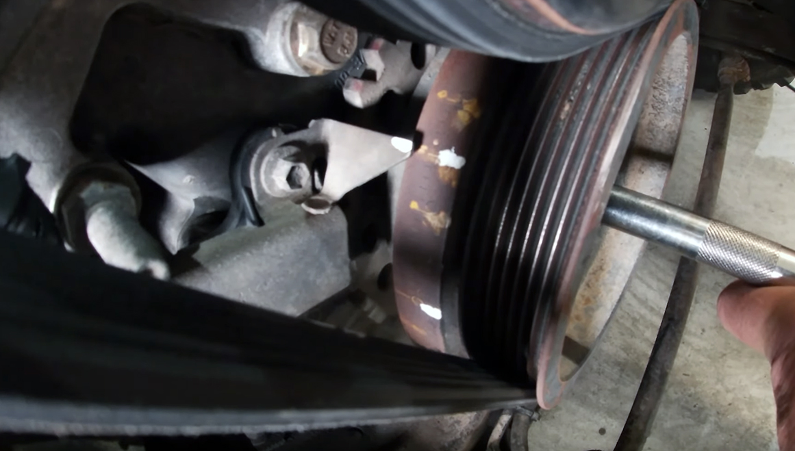
We then wind the engine over to 30 degrees before top dead centre cylinder 1 compression and install the distributor. Remember the distributor will twist when you push it down as it needs to engage with the camshaft drive. You will need to compensate for that twist as you lock it in position. With the distributor correctly installed we need to secure it place using the original locking plate and screw.
The distributor is now mechanically phased but we still need to synchronise the ECU to the engine (that is, the ECU to the trigger pickup). This step needs to be done regardless of whether the engine has a distributor or coil on plug ignition system. To do this, we lock the ECUs ignition timing to the middle of the working range (in our case it was 30 degrees), then we use our timing light to check where the ignition timing is firing.
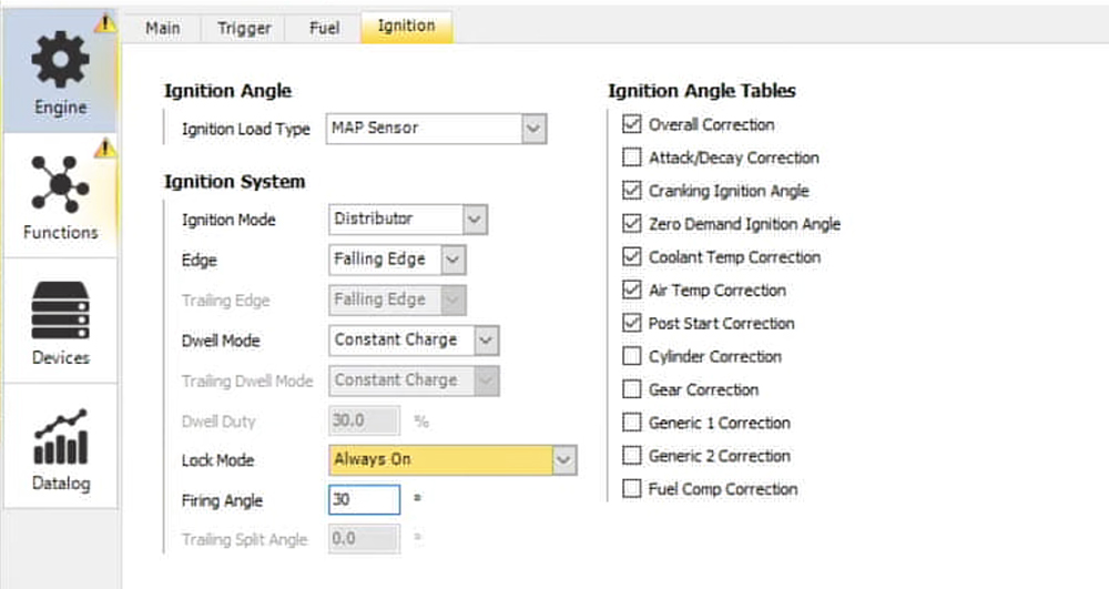
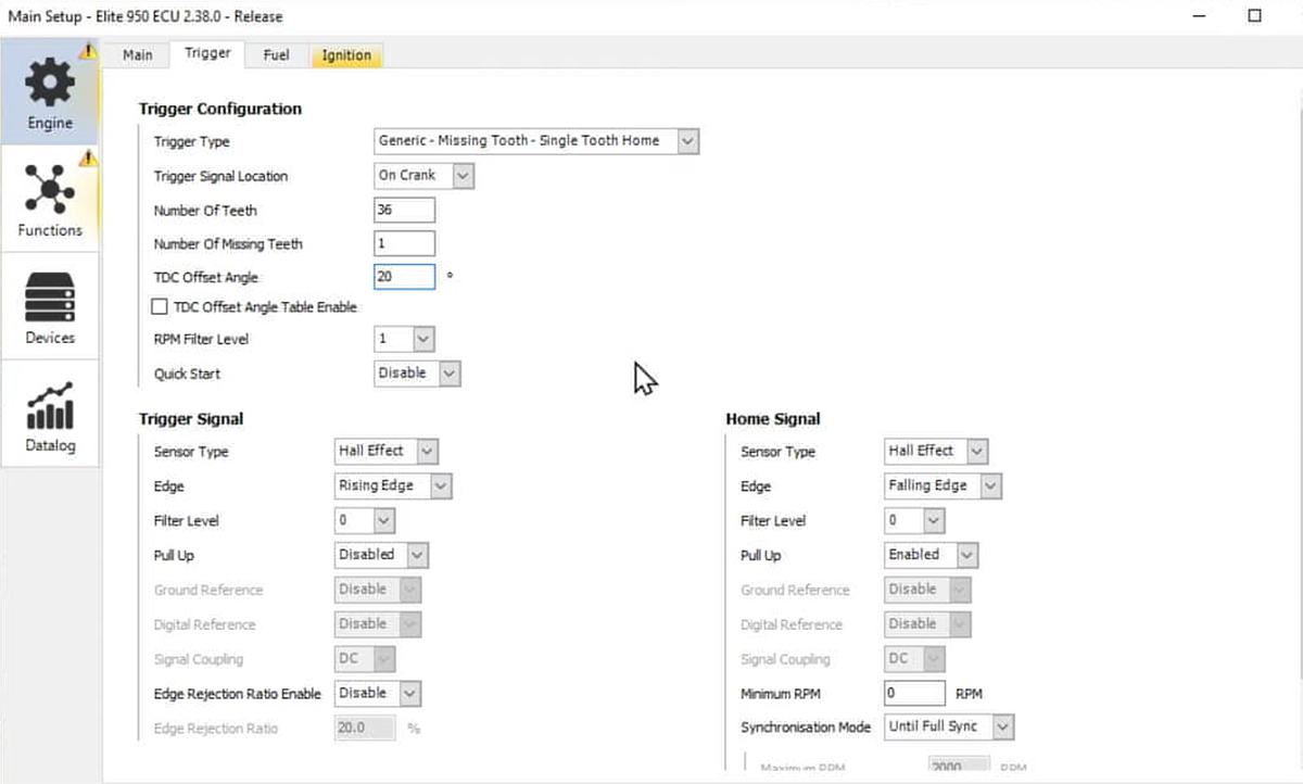
The ECU is getting engine position information from the trigger signal wired into the ECU, but we haven’t told the ECU the position of the engine relative to the trigger tooth and that’s what we need to synchronise. We now adjust the TDC Offset angle until our timing light shows 30 degrees on the crankshaft when we have the pickup over the spark plug lead for cylinder 1.
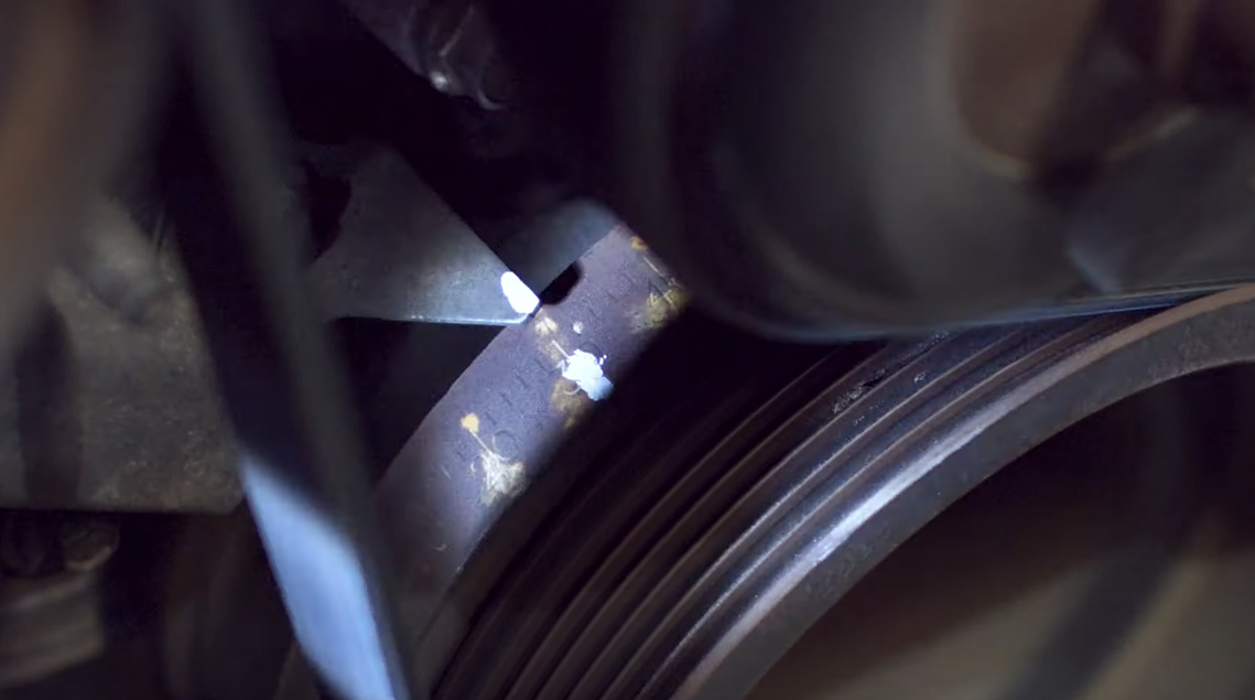
Once the timing light is showing 30 degrees we can fire the engine up (keep in mind some engines won’t like being started with 30 degrees of ignition advance so you may need to unlock the timing to start it, then re-lock the timing once the engine is running).
Rev the engine up and make sure the ignition timing stays consistent and doesn’t cross-fire or misfire. If a misfire occurs it’s an indication of either incorrect rotor phasing or incorrect TDC offset angle. Stop the engine and go back to the beginning of the process.
Always remember to unlock the ignition timing after you have finished the ignition timing synchronisation process, otherwise the ECU will only ever fire at the lock timing value!